
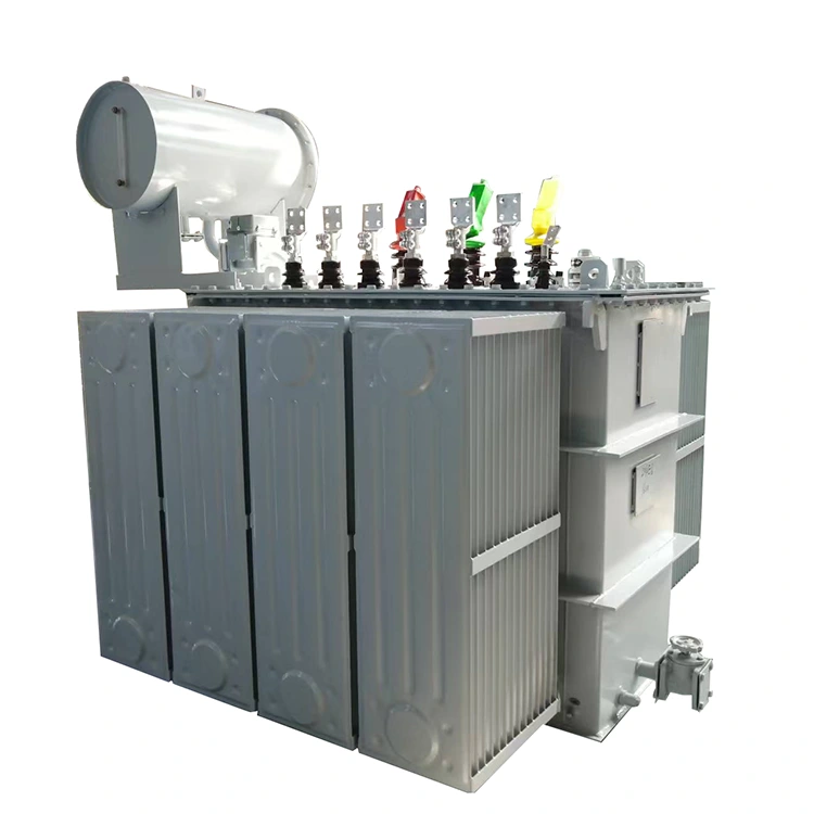
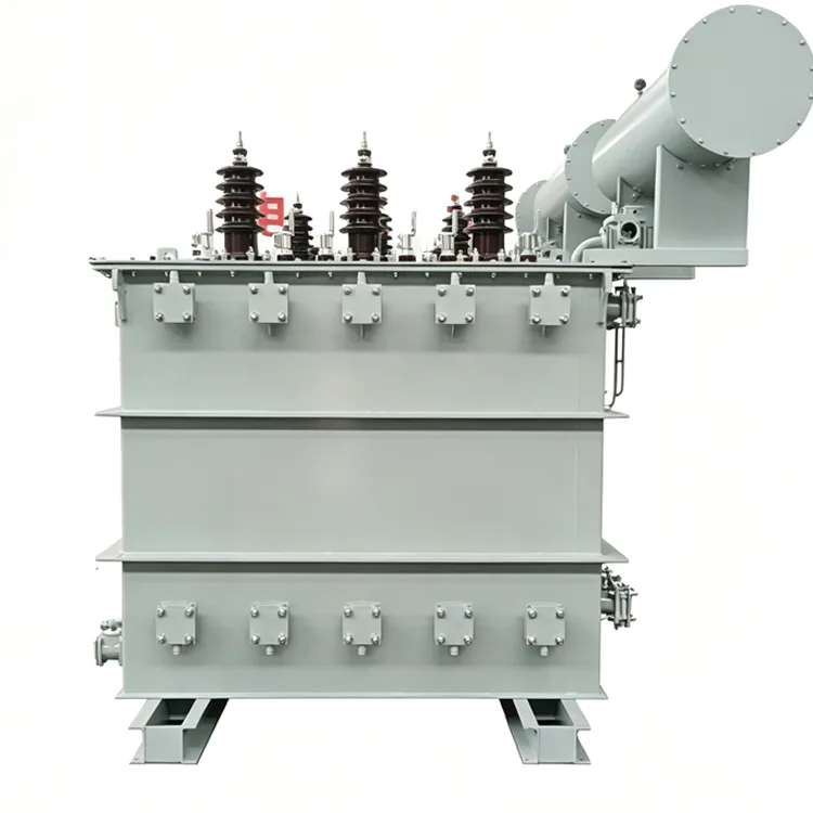
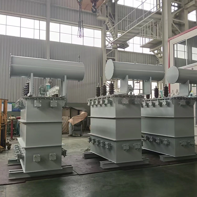
12-Pulse Rectifier Transformer
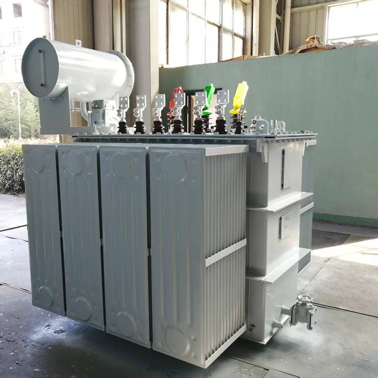
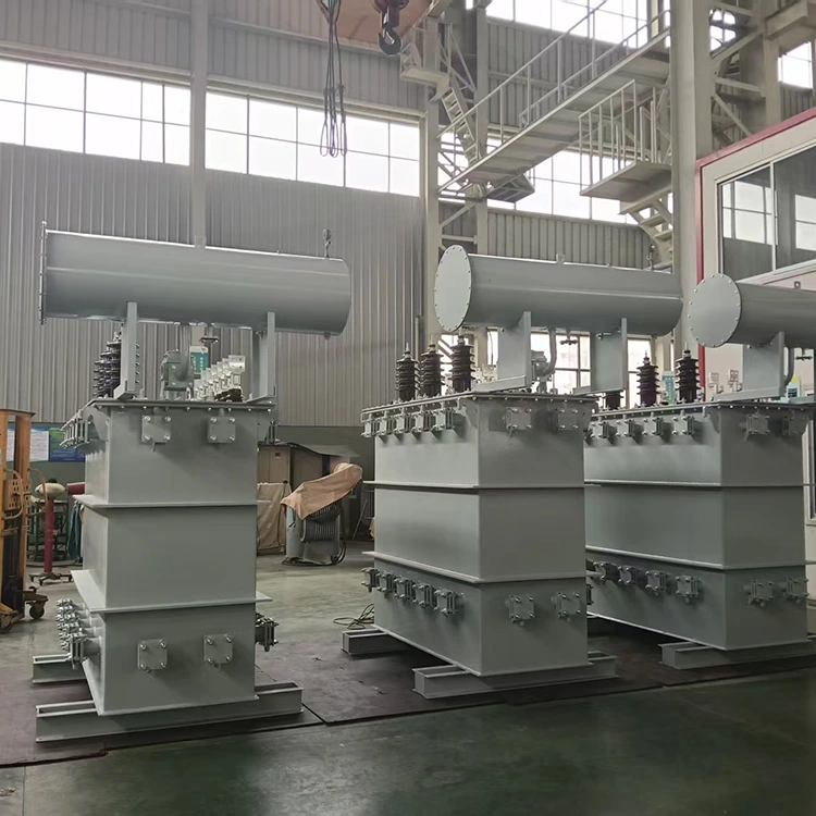
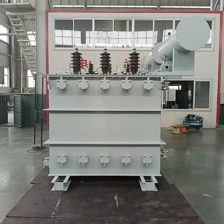
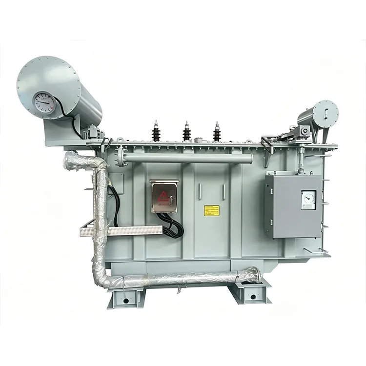
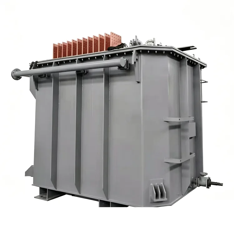
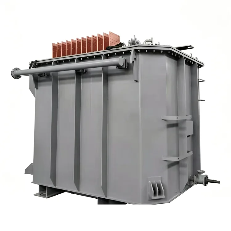
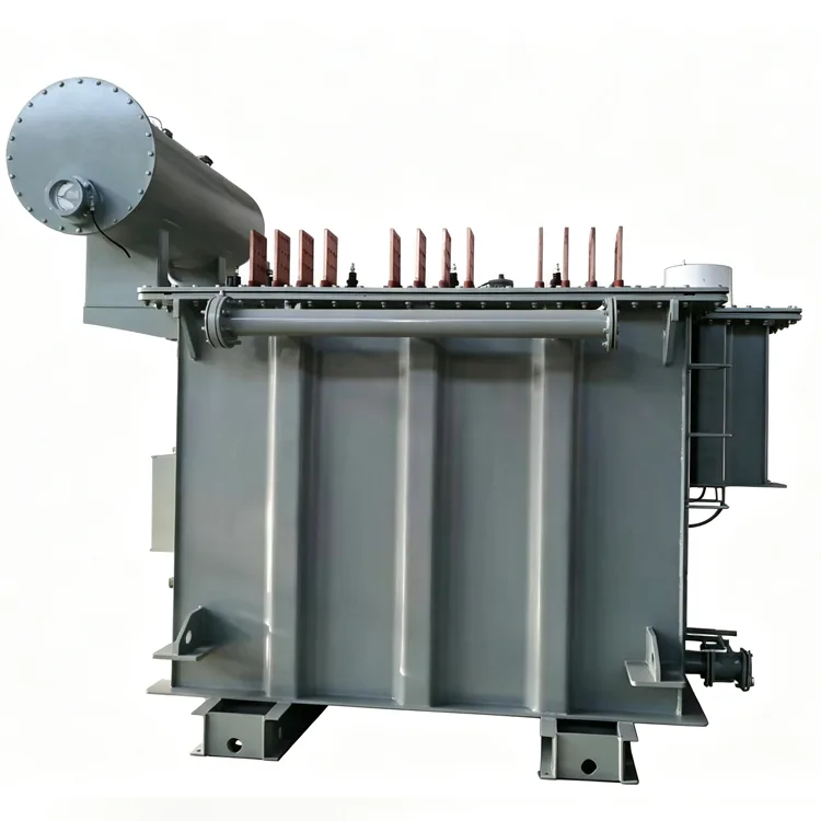
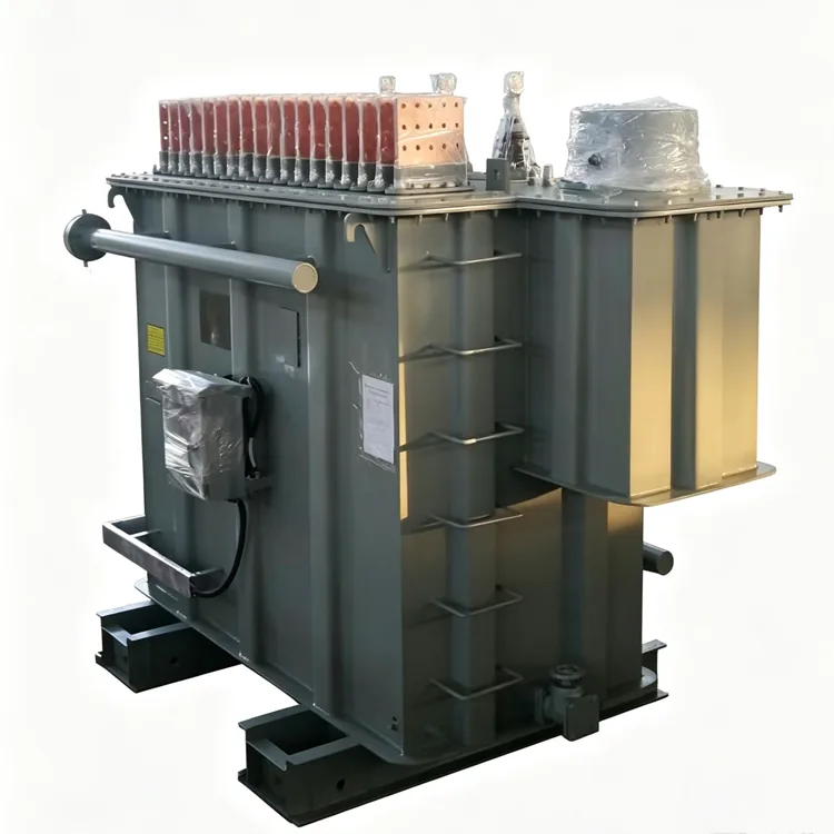
The 12-pulse rectifier transformers manufactured by Yulan are specifically designed to mitigate 5th and 7th harmonics in high-power rectification systems. This product series offers rated capacities ranging from 630 kVA to 80,000 kVA and grid-side voltages between 6 kV and 35 kV, making them suitable for electrolysis, rail transit, and industrial DC power supply systems. Please contact us to request a quote or technical specifications, or to discuss customized solutions.
Harmonic mitigation in rectifier systems typically begins with increasing the pulse number. A 6-pulse rectifier generates low-order harmonics (such as the 5th and 7th) on the grid side, affecting power quality and increasing equipment losses. By powering two 6-pulse rectifier bridges via a phase-shifting transformer — creating a 30 ° phase difference between their AC sides — a 12-pulse output is achieved on the DC side. Theoretically, the 5th and 7th harmonics cancel each other out, leaving the 11th and 13th as the primary residual harmonics, thereby significantly reducing harmonic content. Yulan Transformer ’ s 12-pulse rectifier transformers range from 630 kVA to 80,000 kVA, with grid-side voltage ratings including 6 kV, 10 kV, 15 kV, 22 kV, and 35 kV.
Structural Configurations
There are two common ways to implement a 12-pulse rectifier transformer:
Method 1: Two Independent Transformers
Two 6-pulse rectifier transformers are designed with phase shifts of +15 ° and -15 ° , respectively, and connected in parallel to supply two sets of rectifier bridges. This configuration offers layout flexibility — allowing one unit to operate while the other undergoes maintenance — but requires a larger footprint.
Method 2: Single Transformer with Dual Windings
A single transformer is equipped with two sets of valve-side windings — one star-connected and one delta-connected — naturally creating a 30 ° phase difference. This configuration is compact, though a failure in the single unit affects the entire load.
Users can choose the configuration based on available site space, maintenance strategies, and reliability requirements. Both methods are equivalent in terms of harmonic suppression performance.
Applicable Industries
12-pulse rectifier solutions are commonly used in applications with strict limits on grid harmonics, including:
● Urban rail transit traction power supply systems
● Non-ferrous metal electrolysis (e.g., aluminum and copper)
● Chlor-alkali electrolysis in the chemical industry
● Power supplies for DC electric arc furnaces
● Large-scale electroplating production lines
Industrial facilities required to meet IEEE 519 or GB/T 14549 harmonic limits
Data Parameters
|
Item |
Parameter |
|
Executive Standard |
IEC, GB, ANSI/IEEE, NEMA, and industry-specific specifications |
|
Rated Capacity |
630 kVA to 80,000 kVA |
|
Grid-side Rated Voltage |
6 kV, 10 kV, 15 kV, 22 kV, 35 kV |
|
Valve-side Rated Voltage |
Determined by the rectifier circuit; common range: 380 V to 3,000 V |
|
Rated Frequency |
50 Hz / 60 Hz |
|
Number of Phases |
Three-phase |
|
Phase-shift Angle |
±15 ° , 0 ° /30 ° , or other (per system requirements) |
|
Grid-side Connection |
D or Y |
|
Valve-side Connection |
y, d, or dual-winding |
|
Short-circuit Impedance |
6% to 12% or per rectifier requirements |
|
Cooling Method |
ONAN, ONAF, OFWF |
|
Voltage Regulation Method |
Off-circuit tap changing or on-load tap changing |
Phase-Shifting Winding Design
The phase-shift angle is achieved by adjusting the winding connection configuration. Common phase-shifting methods include extended-delta connections and zigzag connections. The number of turns in the phase-shifting windings must be calculated precisely; excessive deviation in the phase-shift angle can increase circulating currents between the two rectifier bridges, thereby compromising harmonic cancellation performance. Standards typically require the phase-shift angle deviation to be controlled within ± 0.5 ° .
For configurations involving two separate transformers, the short-circuit impedance of both units must be closely matched; excessive deviation leads to uneven load distribution and reduces the harmonic suppression capability of the 12-pulse system. Yulan Transformer verifies the phase-shifting winding turn counts for each individual unit during the winding and assembly processes, and measures the actual phase-shift angle during factory acceptance testing, recording the results in the test report.
Losses and Temperature Rise
While 12-pulse rectifier transformers eliminate the 5th and 7th harmonics — resulting in lower additional winding losses compared to 6-pulse systems — the 11th and 13th harmonics persist. Consequently, the design must still account for eddy current losses. The operating magnetic flux density of the core is kept lower than that of standard distribution transformers to prevent saturation caused by DC bias during rectifier transient processes.
Load losses are slightly lower than those of 6-pulse transformers of the same capacity, with the specific difference depending on the phase-shifting method and winding structure. Customers may request loss calculations and estimated temperature rise data during the technical proposal stage.
Manufacturing and Testing
After the active part is assembled, it undergoes treatment in a kerosene vapor phase vacuum drying system. For high-capacity units, the valve-side windings utilize transposed conductors or multiple parallel conductors, with transposition structures incorporated at the winding ends. Magnetic shielding is installed on the inner walls of the tank — configured according to the unit's capacity — to reduce stray losses caused by harmonic magnetic fields.
In addition to standard items, factory acceptance tests include phase-shift angle measurement, insulation tests between valve-side windings, and partial discharge measurement. For units rated at 35 kV and above, lightning impulse tests are conducted in accordance with relevant standards. Test data is archived by serial number, ensuring traceability back to the winding and core stacking stages.
FAQ
Q: Does a 12-pulse rectifier transformer system necessarily require two transformers?
Not necessarily. A single transformer equipped with two sets of valve-side windings — one wye-connected and one delta-connected — can achieve a 30 ° phase shift, enabling 12-pulse rectification. Alternatively, using two independent transformers distributes the phase-shifting function across two units, facilitating separate operation and maintenance.
Q: How does phase-shift angle accuracy affect the system?
Deviations in the phase-shift angle disrupt the symmetry between the two rectifier bridges, causing DC-side imbalance and preventing the complete cancellation of 5th and 7th harmonics on the grid side. When the deviation is controlled within ± 0.5 ° , harmonic suppression performance generally meets engineering requirements.
Q: How much higher is the cost of a 12-pulse system compared to a 6-pulse system?
The cost increase stems primarily from the complexity of designing and manufacturing phase-shifting windings. A single-unit, dual-winding configuration costs 15% to 25% more than a 6-pulse transformer of the same capacity; a two-unit independent configuration also entails additional costs for switchgear and floor space. However, savings on filtering equipment and maintenance costs may offset the price difference in some projects.
Q: Can an existing 6-pulse system be retrofitted into a 12-pulse system?
Retrofitting options are limited. If the original transformer already includes phase-shifting windings or a dual-winding structure, the conversion might be achieved by adjusting external wiring. Otherwise, the transformer must be replaced, as phase-shifting windings must be incorporated during the manufacturing stage.
Q: For which capacity ranges are 12-pulse rectifier transformers suitable?
Designs are available for capacities above 630 kVA. A single-unit, dual-winding structure is more economical for lower capacities, whereas a two-unit independent transformer configuration is often preferred for higher capacities to facilitate transport and maintenance. The specific choice depends on project layout and reliability requirements.
Engineering Capabilities
Yulan Transformer has been manufacturing electric furnace transformers and rectifier transformers since 1999, possessing the capabilities to manufacture and test products rated at 110 kV and below. Key equipment includes an 80-ton lifting capacity, a 400 kW kerosene vapor phase vacuum drying system, 1200 kV impulse testing equipment, and a 400 kV partial-discharge-free power-frequency test transformer. These facilities enable the company to meet insulation processing and factory acceptance testing requirements for high-capacity 12-pulse rectifier transformers. Please contact the Yulan Transformer technical department for project-specific phase-shifting solutions, loss calculation reports, or outline drawings.
Related Category
Send Inquiry
Contact Info
-
Address
No. 20, Bai'e Road, Hecun Town, Jiangshan City, Zhejiang Province,CHINA
-
Tel
-
Email
Send specs for power, furnace or rectifier transformers and get a customized quotation and price list, direct from Yulan Transformer factory. Bulk orders welcome.
News Recommendations




