
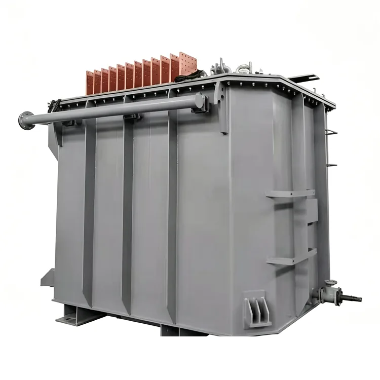
Submerged Arc Furnace Transformer
Yulan Transformer offers submerged arc furnace transformers with rated capacities ranging from 1,000 kVA to 80,000 kVA, designed for ferroalloy, calcium carbide, and industrial silicon smelting processes. This product series supports primary voltages of 6–110 kV, high secondary currents, flexible voltage regulation, and forced cooling capabilities. We invite you to request a quote, review technical specifications, or discuss your specific requirements.
A submerged arc furnace (SAF) — also known as an electric furnace for smelting — is used to produce ferroalloys, calcium carbide, industrial silicon, and similar products. Its transformer differs from that of a standard electric arc furnace (EAF) in terms of load characteristics: in an SAF, the electrodes are submerged in the furnace charge, and heat is generated primarily through the resistance of the charge itself, with arc discharge playing a secondary role. Consequently, the load is relatively stable, yet the secondary current is extremely high and the power factor is low; this necessitates specific designs regarding voltage regulation ranges and impedance.
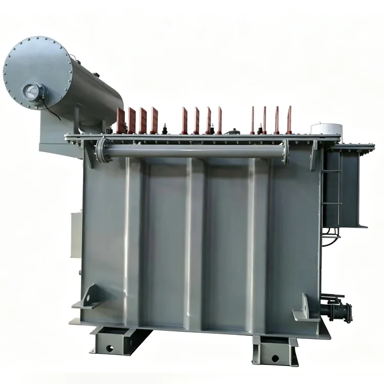
Yulan Transformer manufactures Submerged Arc Furnace Transformer s with capacities ranging from 1,000 kVA to 80,000 kVA. Primary voltages can accommodate 6 kV, 10 kV, 15 kV, 22 kV, 35 kV, and 110 kV, while secondary voltages and the number of voltage regulation steps are determined based on the furnace type and the specific material being smelted.
Load and Design Characteristics
High Current, Moderate Voltage
The secondary voltage of an SAF typically ranges from 100 V to 300 V — higher than that of an EAF but lower than that of a calcium carbide furnace. Secondary currents can reach tens of thousands of amperes; windings utilize multiple parallel conductors or transposed conductors, and output leads consist of multi-layer copper busbars.
Low Power Factor
Variations in the resistance of the furnace charge result in an inductive load, with the power factor typically falling between 0.7 and 0.8. Transformer design must account for reactive power requirements, and some projects incorporate compensation devices on the system side.
Relatively Stable Load
Unlike the violent short-circuit surges seen in EAFs, SAFs experience smaller current fluctuations; however, they operate at full load for extended periods, leading to significant heat accumulation. Windings and cores must be verified for temperature rise under continuous high-current operating conditions.
Wide Voltage Regulation Range
Different smelting stages require different voltages; on-load tap-changing (OLTC) typically involves 13 to 27 steps, with some large calcium carbide furnaces requiring even more. The tap changer must be capable of frequent operation and sustained current-carrying capacity.
Technical Parameters
|
Item |
Parameter Range |
|
Executive Standard |
IEC 60076 series, GB/T 10229, JB/T 5347, and user technical specifications |
|
Rated Capacity |
1,000 kVA to 80,000 kVA |
|
Primary Rated Voltage |
6 kV, 10 kV, 15 kV, 22 kV, 35 kV, 110 kV |
|
Secondary Voltage |
100 V to 300 V (segmented based on furnace type and smelting product) |
|
Number of Voltage Regulation Steps |
13 to 27 steps (19 steps commonly used) |
|
Rated Frequency |
50 Hz / 60 Hz |
|
Number of Phases |
Three-phase (except for some single-phase furnaces) |
|
Vector Group |
Dd0, Yd11, D-Yd0-11, etc. |
|
Short-Circuit Impedance |
6% to 15% (based on maximum secondary voltage) |
|
Cooling Method |
OFWF, OFAF, ONAF (depending on capacity and loss density) |
|
Voltage Regulation Method |
Mainly on-load tap-changing; off-circuit tap-changing available for small capacities |
Representative Models and Reference Data
|
Model |
Rated Capacity (kVA) |
Primary Voltage (kV) |
Secondary Voltage (V) |
Voltage Regulation Steps |
Short-circuit Impedance (%) |
Cooling Method |
|
HSSPZ-6300/10 |
6300 |
10 |
180-100 |
15 |
8 |
ONAF |
|
HSSPZ-10000/35 |
10000 |
35 |
220-120 |
19 |
8.5 |
ONAF |
|
HSSPZ-16000/35 |
16000 |
35 |
240-130 |
19 |
9 |
OFAF |
|
HSSPZ-25000/35 |
25000 |
35 |
260-140 |
21 |
9.5 |
OFWF |
|
HSSPZ-40000/35 |
40000 |
35 |
280-150 |
23 |
10 |
OFWF |
|
HSSPZ-63000/110 |
63000 |
110 |
300-160 |
27 |
11 |
OFWF |
Note: The primary voltage can be designed between 6 kV and 110 kV according to user requirements, with corresponding adjustments to impedance and external dimensions.
Design Highlights
Windings and Leads
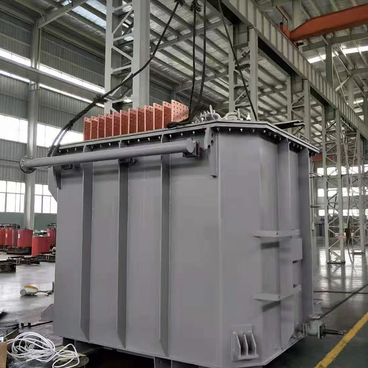
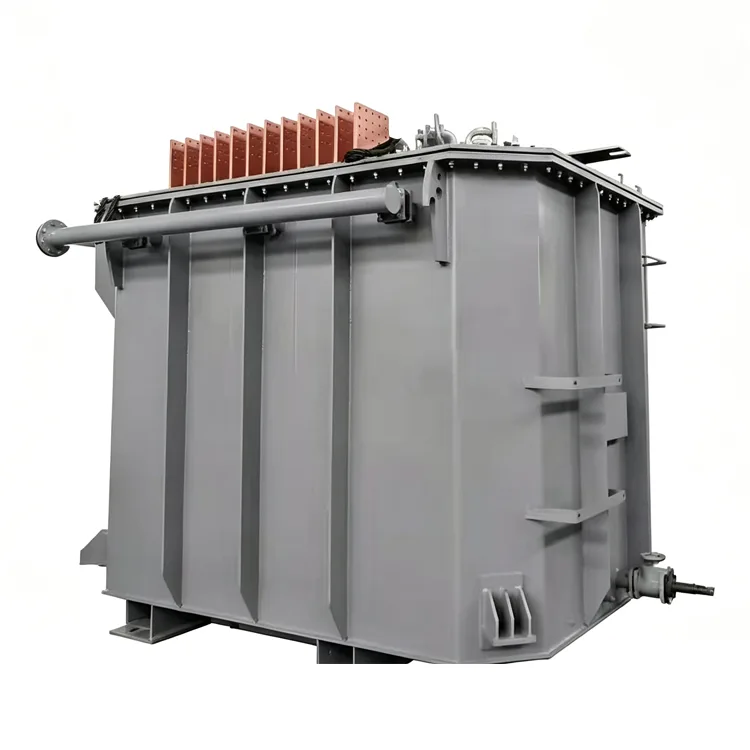
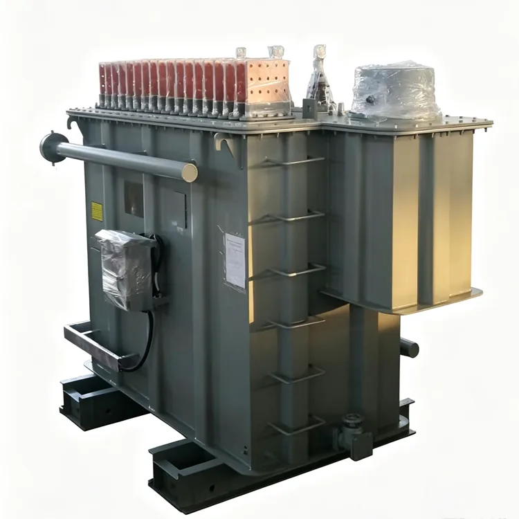
The secondary winding utilizes transposed conductors, with transposition of multiple parallel branches at the ends to ensure uniform current distribution. Multi-layer copper busbars are used for the lead-outs, with adjacent busbars carrying current in opposite directions to reduce the external magnetic field. Large-area terminal boards are installed on the tank sidewalls to minimize contact resistance.
Impedance Selection
Submerged-arc furnace transformers typically feature higher impedance than power transformers of the same capacity to limit short-circuit currents and improve furnace operating conditions. Specific values are determined by the furnace manufacturer and electrical designers based on grid short-circuit capacity and the smelting process. High impedance reduces effective input power, while low impedance increases current fluctuations; a balanced value must be selected.
On-Load Tap Changer (OLTC)
Large-capacity submerged-arc furnace transformers almost exclusively employ on-load voltage regulation. Given the high frequency of tap-changer operations, a model suitable for frequent switching must be selected, and an independent oil filtration system should be installed. Some users employ a combination of coarse and fine regulation to reduce wear on tap-changer contacts.
Cooling System
Due to high loss density, forced oil circulation with water cooling or air cooling is commonly used. In water-cooling systems, oil pressure must always exceed water pressure to prevent water from leaking into the oil. Cooler selection must account for additional harmonic losses rather than relying solely on calculations based on power-frequency sinusoidal current.
Harmonics and Additional Losses
Submerged-arc furnace loads contain harmonics; therefore, design margins must be included for conductor cross-sections and structural component shielding. Magnetic or electric shielding is installed on the inner tank walls to reduce stray losses and the risk of local overheating.
Manufacturing and Verification
Yulan Transformer has been manufacturing electric furnace transformers since 1999, supplying SAF transformers to industries such as ferroalloys, calcium carbide, and industrial silicon. The company is equipped with an 80-ton lifting capacity, a 400kW kerosene vapor phase vacuum drying system, 1200kV impulse testing equipment, and a 400kV partial-discharge-free power-frequency test transformer. These facilities enable the insulation processing and factory verification of SAF transformers rated at 110kV and below. Before leaving the factory, every unit undergoes a series of tests, including winding DC resistance, voltage ratio, insulation resistance, power-frequency withstand voltage, induced withstand voltage, no-load loss, load loss, short-circuit impedance, and operational cycle tests for the on-load tap changer.
Selection Q&A
Q: Can submerged-arc furnace transformers and electric arc furnace (EAF) transformers be interchanged?
Generally, they cannot be directly interchanged. Submerged-arc furnace loads are relatively stable, and their impedance and voltage regulation characteristics differ from those of EAFs. EAF transformers are designed to withstand frequent short-circuit shocks, whereas submerged-arc furnace transformers are designed for continuous high-current operation. Interchangeability requires re-verification of impedance, temperature rise, and mechanical strength.
Q: Is a higher number of voltage regulation steps always better?
Not necessarily. A higher number of voltage steps allows for finer voltage regulation and better matching with various smelting stages; however, this entails higher costs for the tap changer and an increase in the transformer tank's physical size. Typically, 19 steps suffice for ferroalloy furnaces, whereas calcium carbide furnaces may require 27 or more steps. The final configuration is determined by the specific furnace process requirements.
Q: Why do submerged arc furnace (SAF) transformers have higher impedance than standard power transformers?
Fluctuations in furnace charge resistance can cause current surges; higher impedance limits peak currents and stabilizes furnace operating conditions. Additionally, high impedance reduces short-circuit currents, thereby protecting the windings. While standard power transformers typically have short-circuit impedance values between 4% and 6%, SAF transformers usually range from 6% to 15%.
Q: What are the advantages of selecting a 110kV primary voltage?
For large-capacity SAF transformers, connecting to a lower primary voltage would result in excessively high primary currents, placing an undue burden on switchgear and cabling. A 110kV rating lowers the primary current and reduces line losses, making it suitable for projects with capacities exceeding 20,000 kVA. However, this choice entails higher insulation costs and a larger footprint, requiring a comprehensive evaluation.
Q: What are the key points for the daily maintenance of the water-cooling system?
Regularly monitor the pressure differential between the oil and water circuits; the oil pressure must remain higher than the water pressure. Scale buildup in the cooler impairs heat dissipation, so cleaning schedules should be determined based on water quality. The cooling system must be activated before the transformer starts up and should continue to operate for a period after the transformer shuts down.
Related Category
Send Inquiry
Contact Info
-
Address
No. 20, Bai'e Road, Hecun Town, Jiangshan City, Zhejiang Province,CHINA
-
Tel
-
Email
Send specs for power, furnace or rectifier transformers and get a customized quotation and price list, direct from Yulan Transformer factory. Bulk orders welcome.
Related Products
News Recommendations




