
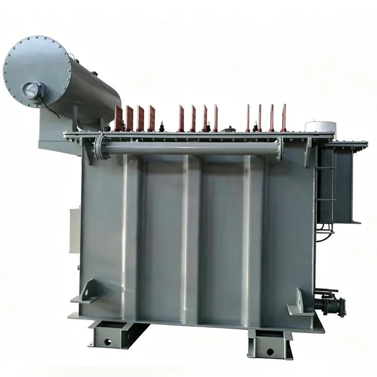
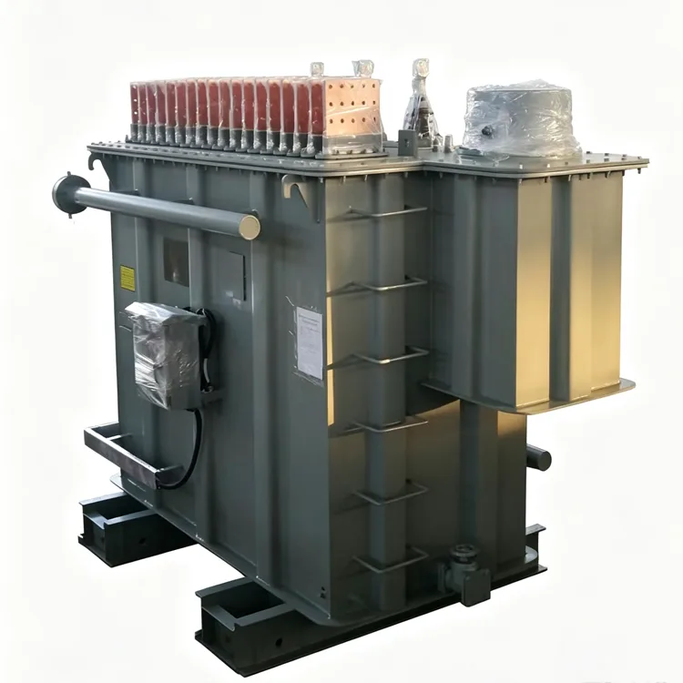
Refining Furnace Transformer
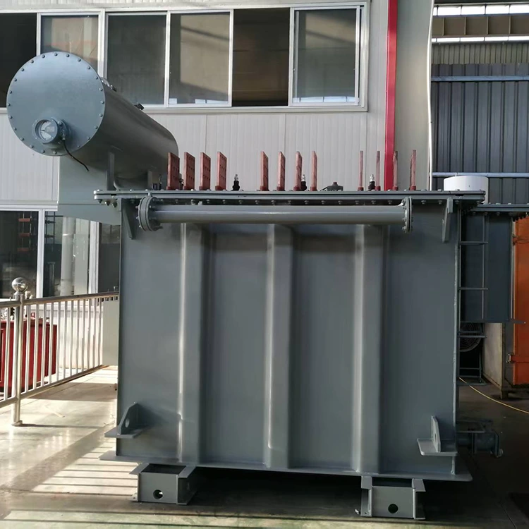
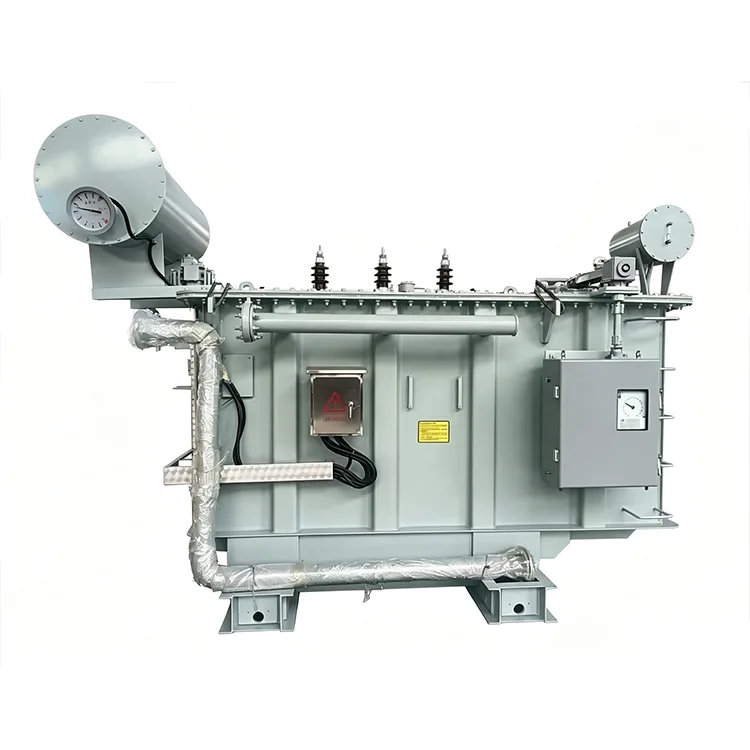
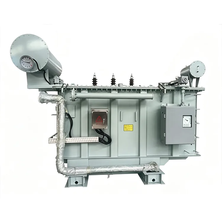
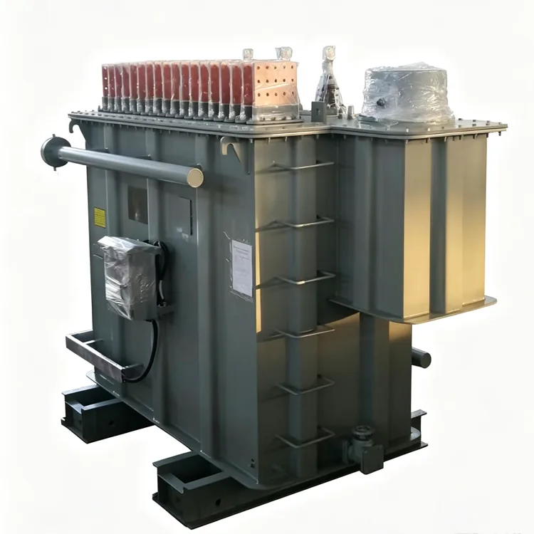
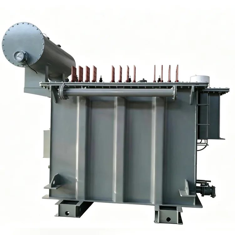
For steel secondary refining processes, Yulan Transformer offers refining furnace transformers with rated capacities ranging from 1,000 to 80,000 kVA. This product series is engineered for precise voltage control, frequent tap-changing, and high-current furnace operations, with configurations customizable to specific process requirements. Please contact us to request a quote, inquire about purchasing, or order a custom transformer.
The refining furnace serves as a secondary processing station in the electric arc furnace (EAF) steelmaking process, responsible for raising the temperature of the molten steel, fine-tuning its chemical composition, and removing inclusions. Compared to transformers used for primary melting EAFs, the associated refining furnace transformers experience less frequent short-circuit surges but require higher precision in voltage regulation and greater operational frequency. Yulan Transformer manufactures refining furnace transformers with capacities ranging from 1,000 kVA to 80,000 kVA; primary voltages can be configured for 6 kV, 10 kV, 15 kV, 22 kV, 35 kV, or 110 kV, while secondary voltages and tap settings are customized according to specific refining process curves.
Operational Differences and Design Priorities
Arc Stability: The refining furnace arc is relatively short and submerged beneath the slag layer; current fluctuations are lower than those in melting furnaces, resulting in relatively moderate mechanical stress on the windings.
Voltage Regulation Frequency: Power adjustments are frequent during the refining stage, with the on-load tap changer potentially operating dozens of times daily; consequently, contact lifespan and switching reliability are key considerations in selection.
Secondary Voltage Range: Typically between 120 V and 280 V — lower than that of melting furnaces but higher than that of calcium carbide furnaces — depending on ladle capacity and electrode diameter.
Impedance Selection: Must balance short-circuit current limitation against voltage drop in the short-network busbars; standard values range from 6% to 10%, requiring coordinated calculation with the furnace's short-network parameters.
Cooling Method: For capacities exceeding 8,000 kVA, loss density increases, necessitating forced oil circulation with air cooling or water cooling. Technical Parameter Range
Item Parameter
|
Item |
Standards |
|
Executive Standard |
IEC 60076, GB/T 10229, JB/T 9640, and user technical specifications |
|
Rated Capacity |
1,000 kVA to 80,000 kVA |
|
Primary Rated Voltage |
6 kV, 10 kV, 15 kV, 22 kV, 35 kV, 110 kV |
|
Secondary Voltage |
120 V to 280 V (stepped according to refining process requirements) |
|
Number of Voltage Regulation Steps |
5 to 19 steps (typically 8 to 13 steps) |
|
Rated Frequency |
50 Hz / 60 Hz |
|
Number of Phases |
Three-phase |
|
Vector Group |
Dd0, Yd11, D-Yd0-11, D-YdD-11, etc. |
|
Short-Circuit Impedance |
6% to 10% (based on the maximum secondary voltage) |
|
Cooling Method |
ONAN, ONAF, OFAF, OFWF |
|
Voltage Regulation Method |
Primarily on-load tap changing; off-circuit electric tap changing available for smaller capacities |
Typical Configuration Reference
The data below is aggregated from multiple projects currently in operation and does not represent a single specific model. Final parameters are subject to the technical agreement and factory documentation.
|
Ladle capacity (t) |
Transformer capacity (kVA) |
Primary voltage (kV) |
Secondary voltage (V) |
Number of taps |
Impedance (%) |
Cooling |
|
30 |
2500 |
10 |
190-120 |
5 |
7 |
ONAN |
|
60 |
5000 |
35 |
210-130 |
7 |
7.5 |
ONAF |
|
80 |
8000 |
35 |
230-140 |
9 |
8 |
ONAF |
|
120 |
12500 |
35 |
250-150 |
11 |
8.5 |
OFAF |
|
150 |
16000 |
35 |
260-160 |
13 |
9 |
OFAF |
|
200 |
25000 |
110 |
270-170 |
15 |
9.5 |
OFWF |
|
300 |
40000 |
110 |
280-180 |
17 |
10 |
OFWF |
Manufacturing and Verification
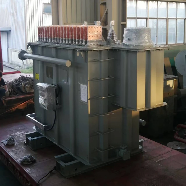
Yulan Transformer has been manufacturing electric furnace transformers since 1999, supplying refining furnace transformers to numerous steel mills across China. Production capabilities include an 80-ton lifting capacity, a 400 kW kerosene vapor-phase vacuum drying system, 1,200 kV impulse testing equipment, and a 400 kV partial-discharge-free power-frequency test transformer. Before leaving the factory, every unit undergoes a comprehensive series of tests, including winding DC resistance, voltage ratio, insulation resistance, power-frequency withstand voltage, induced withstand voltage, no-load loss, load loss, short-circuit impedance, and on-load tap changer (OLTC) operating cycle tests. Test data is archived by serial number, ensuring full traceability back to raw material batches and process records. The company holds ISO 9001:2015, ISO 14001, and ISO 45001 certifications.
Design Details
Short-Network Voltage Drop Compensation
The length and layout of the short network (connecting transformer secondary terminals to electrodes) affect the actual voltage inside the furnace. The voltage drop across the short network must be accounted for when designing the secondary voltage; otherwise, refining power will be insufficient. Users should provide data on short-network impedance and length for winding calculations.
Tap Changer Selection
Refining furnaces require frequent voltage adjustments; standard power transformer tap changers may not meet service life requirements. Vacuum on-load tap changers or high-speed switching types specifically designed for electric furnace transformers are recommended, along with an independent oil filtration system.
Winding Structure
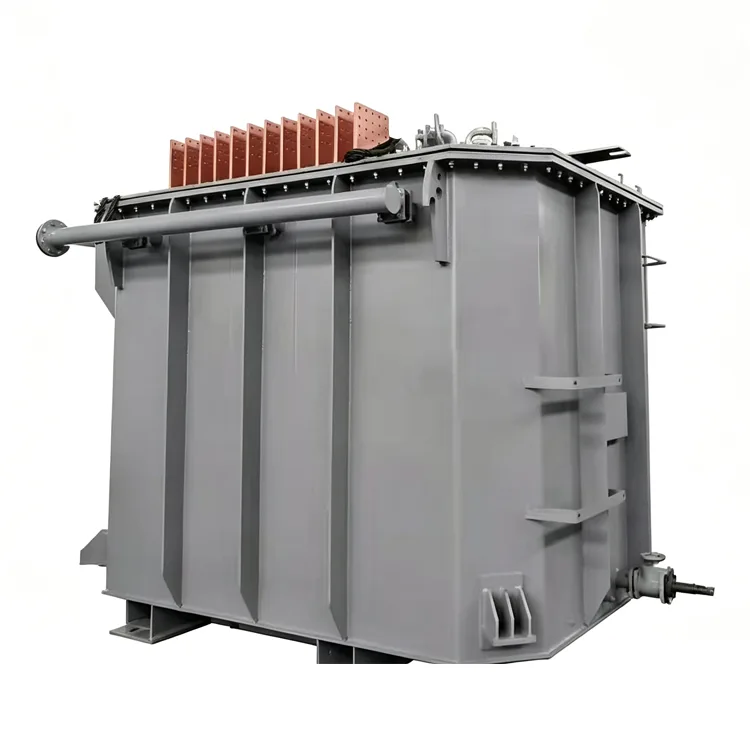
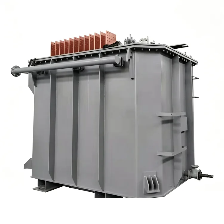
Due to high secondary currents, transposed conductors or multiple parallel conductors are used, with transposition at the ends to ensure current balance. Copper busbars are used for lead-outs in an "in-phase inverse-parallel" configuration to minimize external magnetic fields and heating of structural components.
Heat Accumulation and Insulation
Refining furnaces operate in batches, subjecting the transformer to cyclic heating and cooling. The clamping structure must incorporate a preset clamping force to prevent insulation loosening during thermal cycling. The top-oil temperature rise is verified based on continuous full-load operating conditions; design based on short-term overload is not recommended.
Harmonics and Reactive Power
The non-linear nature of the refining furnace arc generates harmonics, while the power factor is relatively low (0.75 to 0.85). Transformer designs incorporate margins for harmonics regarding conductor cross-sections and shielding, while reactive power compensation is handled on the system side.
Common Questions
Q: Can a refining furnace transformer be used interchangeably with a melting arc furnace transformer?
It is not recommended. Melting furnace transformers feature higher impedance, a wider voltage regulation range, and more rigorous mechanical strength requirements. If a refining furnace transformer is used for melting, it may be damaged by frequent short-circuit shocks. Conversely, while using a melting furnace transformer for refining is feasible, mismatches in voltage regulation precision and the number of tap steps may make power control difficult.
Q: How is the secondary voltage range determined?
The furnace manufacturer provides a voltage curve based on ladle dimensions, electrode diameter, and the steel grades to be refined. The transformer designer then translates this into specific turn counts and tap positions. Modifying the secondary voltage at a later stage would necessitate a redesign of the windings; therefore, confirming parameters during the initial phase is crucial.
Q: Is a water-cooling system necessary for refining furnace transformers?
For capacities below 8,000 kVA, air cooling is usually sufficient. Above this capacity or where installation space is limited, water cooling can reduce the size of the radiator, though it entails higher maintenance requirements. The water-cooling system must ensure that the oil pressure remains higher than the water pressure.
Q: What is the appropriate number of voltage regulation steps for a refining furnace transformer?
Five to eight steps are sufficient for refining ordinary carbon steel, whereas 11 to 15 steps are selected for alloy steel or stainless steel when precise temperature control is required. An excessive number of steps increases the cost and number of potential failure points for the tap changer, so a balance must be struck based on process requirements.
Q: How does the installation environment affect the transformer?
The refining furnace area is characterized by high dust levels and elevated temperatures; the transformer should be located in a well-ventilated area and shielded from direct contact with flying steel slag. Outdoor installations require terminal boxes and control cabinets with higher ingress protection ratings, and the impact of high ambient temperatures on cooling efficiency must be considered.
Related Category
Send Inquiry
Contact Info
-
Address
No. 20, Bai'e Road, Hecun Town, Jiangshan City, Zhejiang Province,CHINA
-
Tel
-
Email
Send specs for power, furnace or rectifier transformers and get a customized quotation and price list, direct from Yulan Transformer factory. Bulk orders welcome.
Related Products
News Recommendations




