
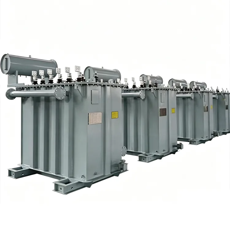
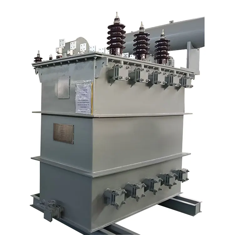
24-Pulse Rectifier Transformer
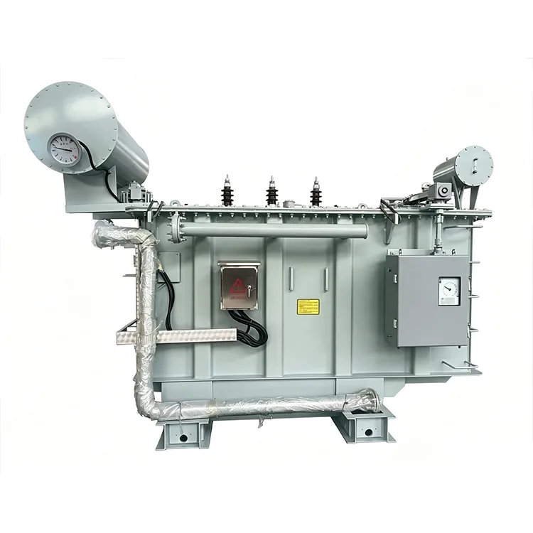
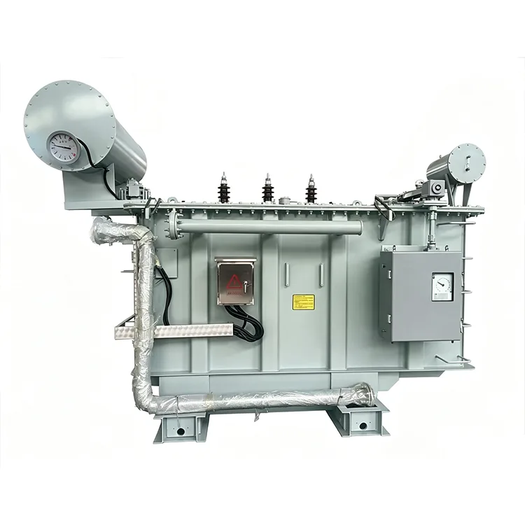
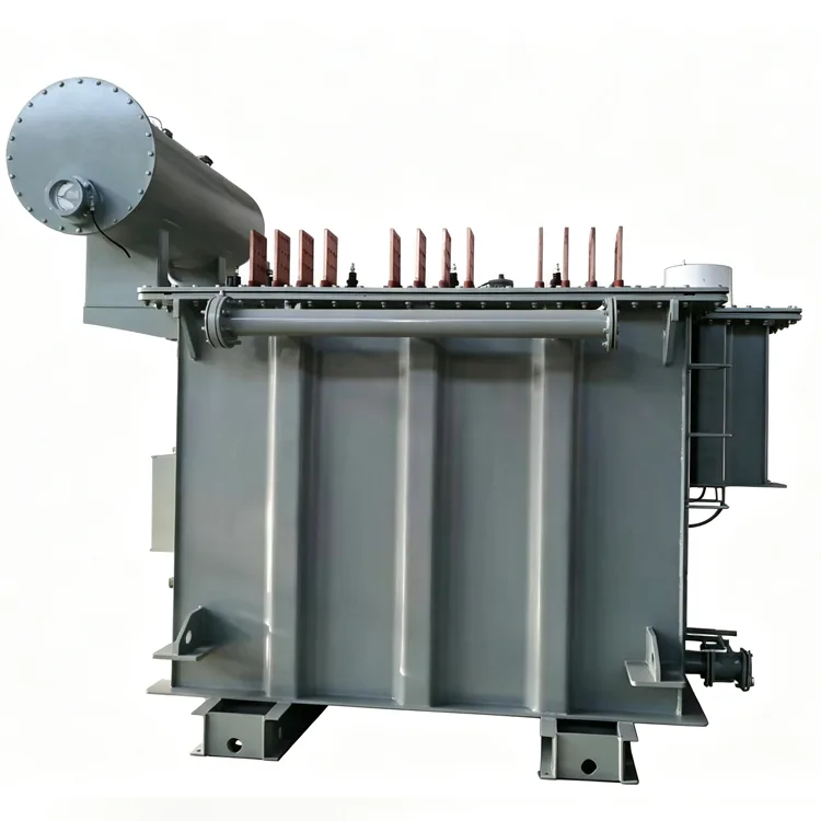
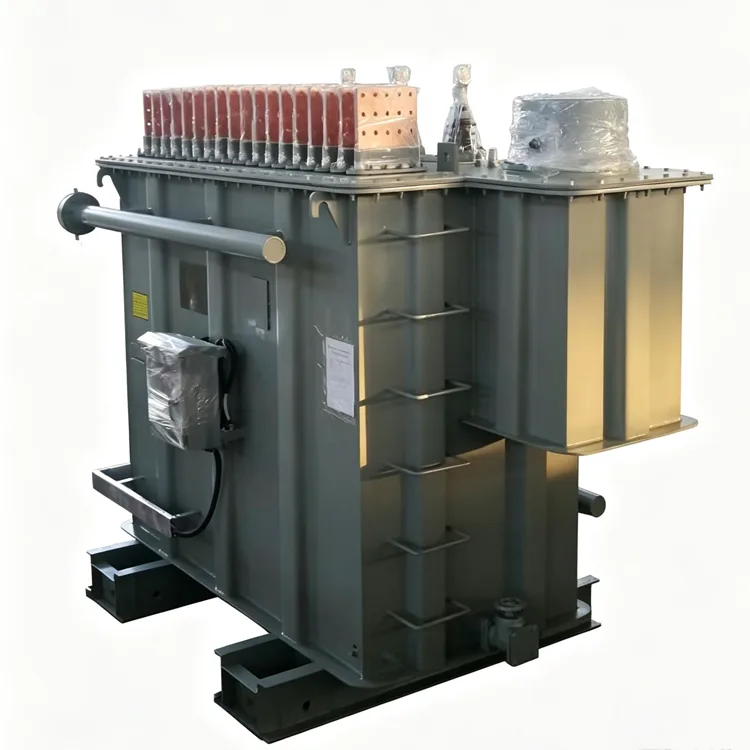
Yulan Transformer 24-pulse rectifier transformer is designed for high-power industrial systems requiring strict harmonic control. Using multi-phase-shift configurations, it reduces low-order harmonics while supporting 630 kVA to 80,000 kVA and 6–35 kV grid-side voltages. Contact us to get a quote, request technical specifications, or discuss a custom solution.
In industrial projects with strict harmonic limitations, while 12-pulse rectification eliminates the 5th and 7th harmonics, the 11th and 13th harmonics persist. When the grid short-circuit capacity is low or power quality requirements are stringent, a 24-pulse scheme can further reduce grid-side harmonic content. Yulan Transformer manufactures 24-pulse rectifier transformers with capacities ranging from 630 kVA to 80,000 kVA; grid-side voltages can accommodate 6 kV, 10 kV, 15 kV, 22 kV, and 35 kV, while valve-side parameters are custom-designed to meet specific rectifier requirements.
Harmonic Cancellation Logic
A 24-pulse rectification system typically consists of four 6-pulse rectifier bridges. A phase-shifting transformer is used to create a sequential 15 ° phase difference between the AC sides of the four bridges. Consequently, most low-order harmonics on the grid side — except for the 23rd and 25th — cancel each other out. Compared to 12-pulse systems, the 11th and 13th harmonics are effectively eliminated; the remaining characteristic harmonics begin at the 23rd order with significantly reduced amplitudes, thereby lessening the demand for filtering equipment.
Common phase-shift combinations used in engineering include +7.5 ° , -7.5 ° , +22.5 ° , and -22.5 ° , or 0 ° , 15 ° , 30 ° , and 45 ° , with the specific configuration determined by the system design.
Implementation Methods
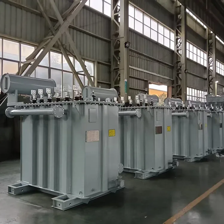
Four Independent Transformers
Four 6-pulse rectifier transformers are designed with specific phase-shift angles, each supplying power to a single rectifier bridge. This scheme offers maintenance flexibility — allowing the remaining units to operate at reduced capacity if one fails — but requires a larger footprint and a greater number of primary-side switchgear units.
Two Dual-Winding Transformers
Each transformer is equipped with two sets of valve-side windings to achieve two distinct phase-shift angles. For example, one transformer outputs +7.5 ° and -7.5 ° , while the other outputs +22.5 ° and -22.5 ° . Compared to the four-transformer scheme, this approach halves the number of units and results in a more compact layout. Single Multi-Winding Transformer
This configuration features four sets of valve-side windings within a single transformer, achieving four phase-shift angles through zigzag or extended-delta connections. While this solution minimizes the equipment footprint, a failure in the single unit affects the entire load, and manufacturing complexity is higher; it is typically used for small-to-medium capacity applications or where space is limited.
Users may select the configuration based on site conditions, maintenance strategies, and reliability requirements. All three methods offer equivalent harmonic suppression performance, with differences primarily lying in physical layout and operation & maintenance.
Technical Specifications
|
Item |
Standards |
|
Executive Standard |
IEC, GB, ANSI/IEEE, NEMA, and industry-specific specifications |
|
Rated Capacity |
630 kVA to 80,000 kVA |
|
Grid-side Rated Voltage |
6 kV, 10 kV, 15 kV, 22 kV, 35 kV |
|
Valve-side Rated Voltage |
Determined by the rectifier circuit; common range: 380 V to 3,000 V |
|
Rated Frequency |
50 Hz / 60 Hz |
|
Number of Phases |
Three-phase |
|
Phase-shifting Configuration |
±7.5 ° , ± 22.5 ° , or other system-specified combinations |
|
Grid-side Connection |
D or Y |
|
Valve-side Connection |
y, d, multi-winding, or zigzag connection |
|
Short-circuit Impedance |
6% to 12% or as required by the rectifier |
|
Cooling Method |
ONAN, ONAF, OFWF |
|
Voltage Regulation Method |
Off-circuit tap changing or on-load tap changing |
Phase-Shift Windings and Accuracy
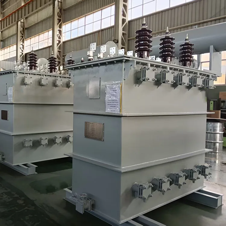
The harmonic cancellation effectiveness of a 24-pulse system relies on the accuracy of the phase difference between bridges. Precise calculation of the phase-shift winding turn ratios is essential, as winding deviations and assembly errors during manufacturing can affect the final phase-shift angle. Yulan Transformer records the turn counts for phase-shift windings on a per-unit basis and verifies inter-winding phase angles during factory acceptance testing, maintaining deviations within ± 0.5 ° .
When using a combination of multiple transformers, the deviation in short-circuit impedance between units must also be controlled. Impedance mismatch leads to uneven load current distribution, potentially overloading specific rectifier bridges and diminishing harmonic cancellation capabilities. Allowable impedance deviation ranges must be clearly defined during the technical design phase.
Losses and Temperature Rise
The 24-pulse scheme eliminates a greater number of harmonic orders, further reducing additional winding losses compared to the 12-pulse scheme. However, since harmonics of the 23rd order and above still induce skin and proximity effects, the conductor design must incorporate sufficient margins. Core magnetic flux density is maintained below the levels typical of conventional distribution transformers to accommodate potential DC components arising during rectifier transients.
Temperature rise tests must be conducted using current waveforms that include the characteristic harmonics; otherwise, the test results will not accurately reflect hot-spot temperature rise under actual operating conditions. Customers may request the harmonic current spectrum when placing an order to serve as input data for temperature rise verification.
Manufacturing and Testing
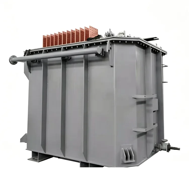
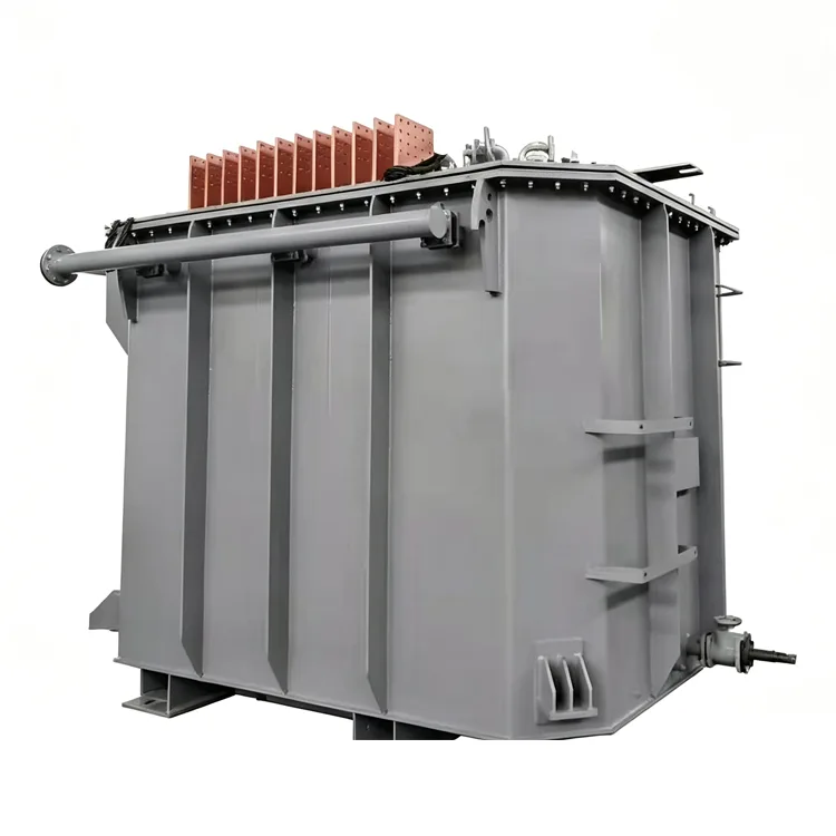
Windings utilize transposed conductors or multiple parallel conductors, while copper busbars are employed for high-current connections on the valve side. Magnetic or electric shielding is installed on the inner walls of the tank — sized according to the transformer's capacity — to minimize stray losses caused by harmonic magnetic fields. High-capacity units are equipped with panel-type radiators or forced oil circulation cooling systems.
In addition to standard routine tests, factory acceptance tests focus on phase-shift angle measurement, insulation tests between valve-side windings, partial discharge measurement, and lightning impulse testing (for 35kV and above). Test data is archived by serial number, ensuring traceability back to processes such as winding fabrication, core stacking, and active part drying.
Engineering Capabilities
Yulan Transformer has been manufacturing electric furnace transformers and rectifier transformers since 1999, possessing the capability to manufacture and test products rated at 110 kV and below. Key equipment includes an 80-ton lifting capacity, a 400 kW kerosene vapor phase vacuum drying system, 1200 kV impulse testing equipment, and a 400 kV partial-discharge-free power-frequency test transformer. These facilities enable the company to meet the insulation processing and factory verification requirements for the complex multi-winding structures of 24-pulse rectifier transformers.
Frequently Asked Questions
Q: What is the difference in harmonic content between 24-pulse and 12-pulse systems?
The primary harmonics in a 12-pulse rectifier are the 11th and 13th orders; a 24-pulse system effectively eliminates these, with residual characteristic harmonics beginning at the 23rd order. The Total Harmonic Distortion (THD) of the grid-side current typically drops from 8% – 10% (12-pulse) to below 4% (24-pulse), with specific values depending on load and impedance.
Q: What happens if one transformer fails in a four-transformer configuration?
In a configuration using four independent transformers, the remaining three can continue to operate if one is taken offline; however, grid-side imbalance will occur, and certain low-order harmonics will reappear. Under these conditions, the total load should be reduced, and maintenance scheduled promptly. In contrast, a single multi-winding transformer configuration does not allow for the isolation of an individual bridge, resulting in a wider impact in the event of a fault.
Q: Is a 24-pulse system more sensitive to phase-shift angle errors than a 12-pulse system?
Yes. A 24-pulse system requires precise phase relationships among four bridge sets simultaneously; a deviation in any single set prevents the corresponding harmonic pairs from fully canceling each other out. Consequently, there are stricter requirements regarding the manufacturing precision and factory testing of the phase-shifting windings.
Q: Is it worth using a 24-pulse system for small-capacity projects?
If the power grid imposes strict harmonic requirements and the cost of filtering is high, a 24-pulse system may be more economical than a 12-pulse system combined with filters. However, for smaller capacities, the fixed costs associated with multiple transformers represent a larger proportion of the total, necessitating a comprehensive cost-benefit analysis. While systems rated above 630 kVA are typically candidates for evaluation, the final choice depends on specific grid conditions and the project budget.
Q: Can a 24-pulse rectifier transformer replace passive filters?
It cannot serve as a complete replacement. Although a 24-pulse system eliminates the majority of low-order harmonics, harmonics of the 23rd order and above persist; furthermore, load imbalances or phase-shift errors can introduce small amounts of low-order harmonics. Some projects may still require a limited number of filter branches, though the capacity and cost involved are significantly lower than those of 6-pulse or 12-pulse solutions.
Related Category
Send Inquiry
Contact Info
-
Address
No. 20, Bai'e Road, Hecun Town, Jiangshan City, Zhejiang Province,CHINA
-
Tel
-
Email
Send specs for power, furnace or rectifier transformers and get a customized quotation and price list, direct from Yulan Transformer factory. Bulk orders welcome.
News Recommendations




