
6-Pulse Rectifier Transformer
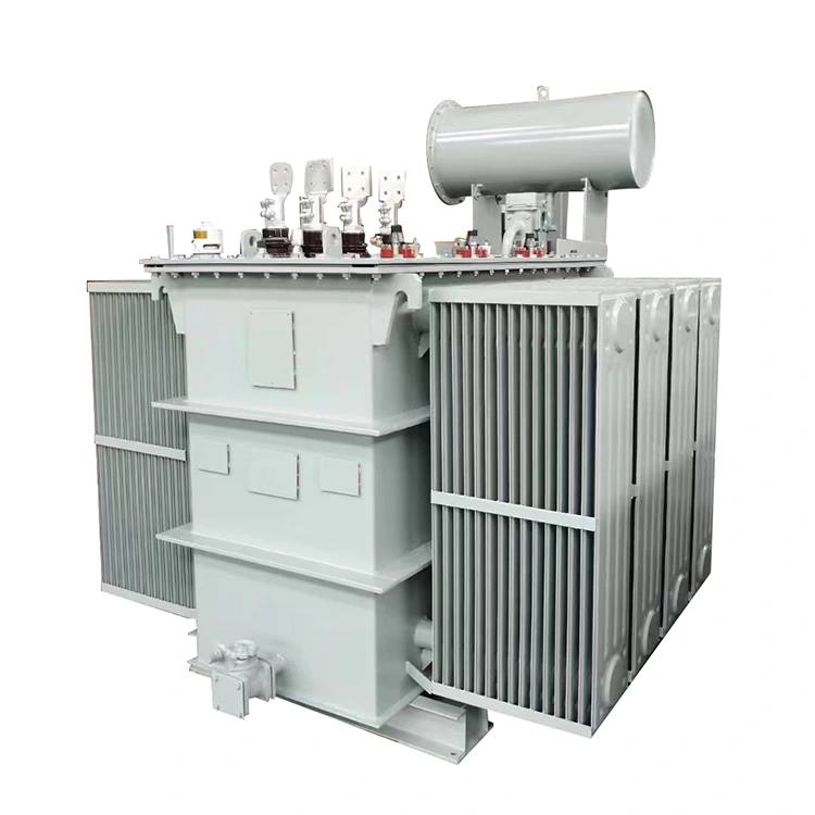
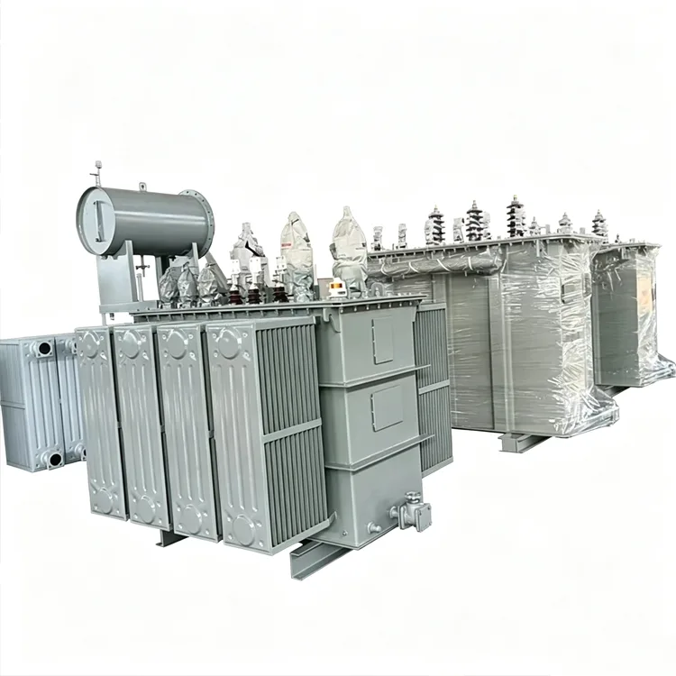
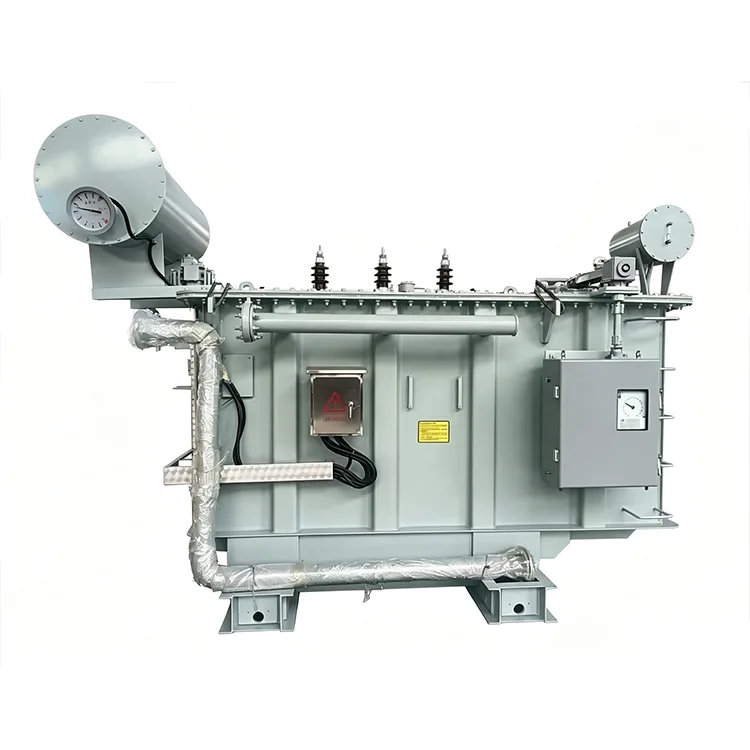
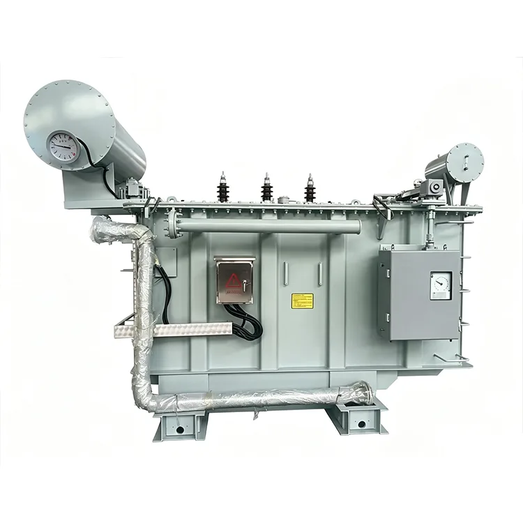
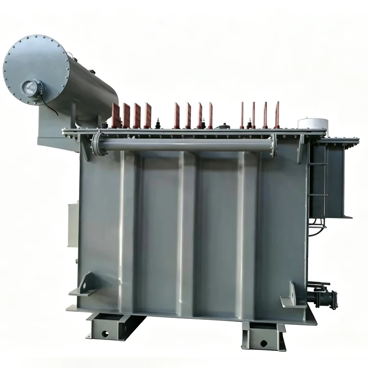
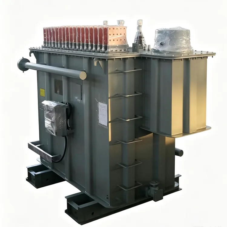
Yulan Transformer supplies 6-pulse rectifier transformers with capacities ranging from 630 kVA to 80,000 kVA, suitable for applications such as electrolysis, electric furnaces, electroplating, and DC power supplies. These products are specifically designed for harmonic loads and can meet customized impedance requirements. Please contact us for quotations, technical support, and project-specific solutions.
6-The primary difference between a rectifier transformer and a conventional distribution transformer lies in the load-side connection to a rectifier; the current waveform is non-sinusoidal with high harmonic content, requiring the windings and core to be designed specifically for rectifier operating conditions. Yulan Transformer possesses extensive manufacturing experience in electric furnace and rectifier transformers. Our 6-pulse rectifier transformers cover a capacity range of 630 kVA to 80,000 kVA, with primary (grid-side) voltages compatible with 6 kV, 10 kV, 15 kV, 22 kV, and 35 kV systems, while secondary (valve-side) parameters are determined by the specific rectifier circuit configuration.
Application Industries
6-pulse rectifier transformers are primarily used in three-phase bridge rectifier systems to supply power to DC loads. Common installation scenarios include:
● Electrolytic processes for non-ferrous metals (aluminum, copper, zinc, etc.)
● Surface treatment production lines (electroplating, anodizing, etc.)
● Graphitization furnaces and industrial electric heating equipment
● Traction rectifier stations for urban rail transit
● Power supplies for DC electric arc furnaces and submerged arc furnaces
● Chemical electrolytic cells and the chlor-alkali industry
These applications share common characteristics: high load currents, varying requirements for DC-side ripple, and specific demands regarding transformer impedance and short-circuit withstand capability.
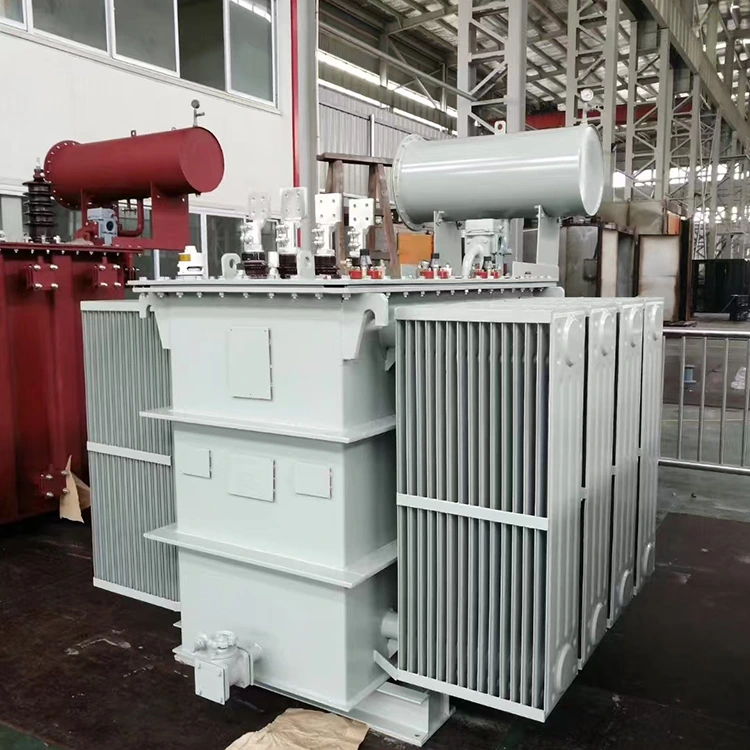
Design Highlights
Winding Structure
The grid-side winding is designed according to the system voltage level, while the valve-side winding is determined by the rectifier's AC input voltage. 6-pulse rectification typically employs Dyn or Yd connections to provide the three-phase AC output required for the three-phase bridge rectifier. Some projects require parallel valve-side windings to reduce the current in individual windings.
Harmonics and Additional Losses
Under rectifier loads, the winding current contains characteristic harmonics (such as the 5th and 7th), which generate additional losses in the windings and structural components. Design measures — such as increasing conductor cross-sections, installing shielding, or using transposed conductors — are employed to minimize eddy current losses and the risk of localized overheating.
Impedance Design
The selection of short-circuit impedance directly affects the rectifier's commutation process, short-circuit current levels, and DC output voltage regulation. Excessive impedance leads to a significant DC voltage drop, whereas insufficient impedance may cause short-circuit currents to exceed the equipment's withstand capacity. The impedance range is typically determined based on parameters provided by the rectifier manufacturer.
Core and Noise
The core is constructed from cold-rolled grain-oriented silicon steel sheets, with the stacking process performed by automated equipment. As the magnetic flux in a rectifier transformer may contain a small DC component, a margin is incorporated into the design regarding the core's operating magnetic flux density to prevent saturation, which would otherwise lead to increased noise and losses.
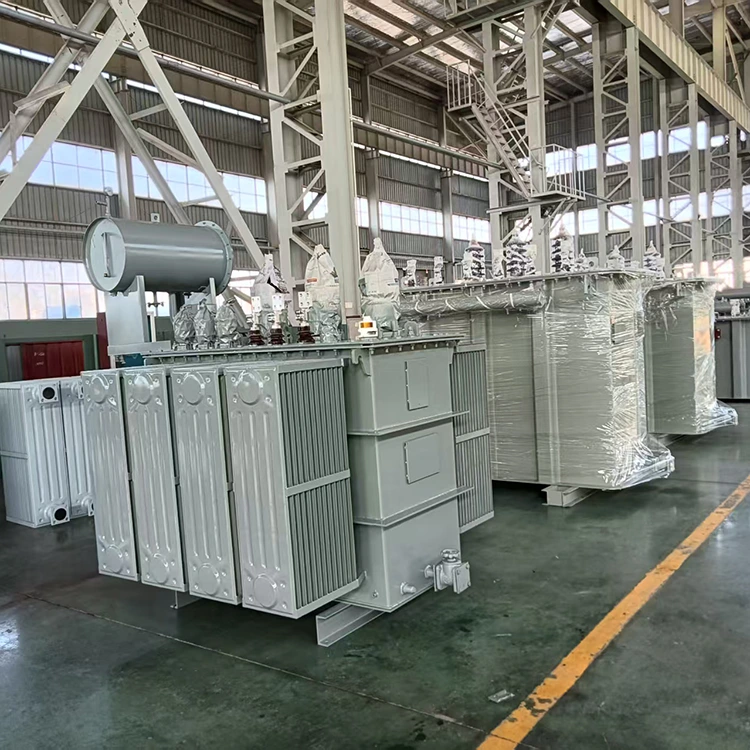
Specifications
|
Item |
Parameter Range |
|
Applicable Standard |
IEC, GB, ANSI/IEEE, NEMA, and industry-specific standards |
|
Rated Capacity |
630 kVA to 80,000 kVA |
|
Grid-side Rated Voltage |
6 kV, 10 kV, 15 kV, 22 kV, 35 kV |
|
Valve-side Voltage |
Determined by rectifier circuit configuration; typically 380 V to 3000 V |
|
Rated Frequency |
50 Hz / 60 Hz |
|
Number of Phases |
Three-phase |
|
Grid-side Connection Group |
D, Y, or per system requirements |
|
Valve-side Connection Group |
y, d, or dual-winding, depending on rectification method |
|
Short-circuit Impedance |
6% to 12%, or designed according to rectifier requirements |
|
Cooling Method |
ONAN, ONAF, or OFWF, depending on capacity and installation conditions |
|
Voltage Regulation Method |
Off-circuit tap changing or on-load tap changing |
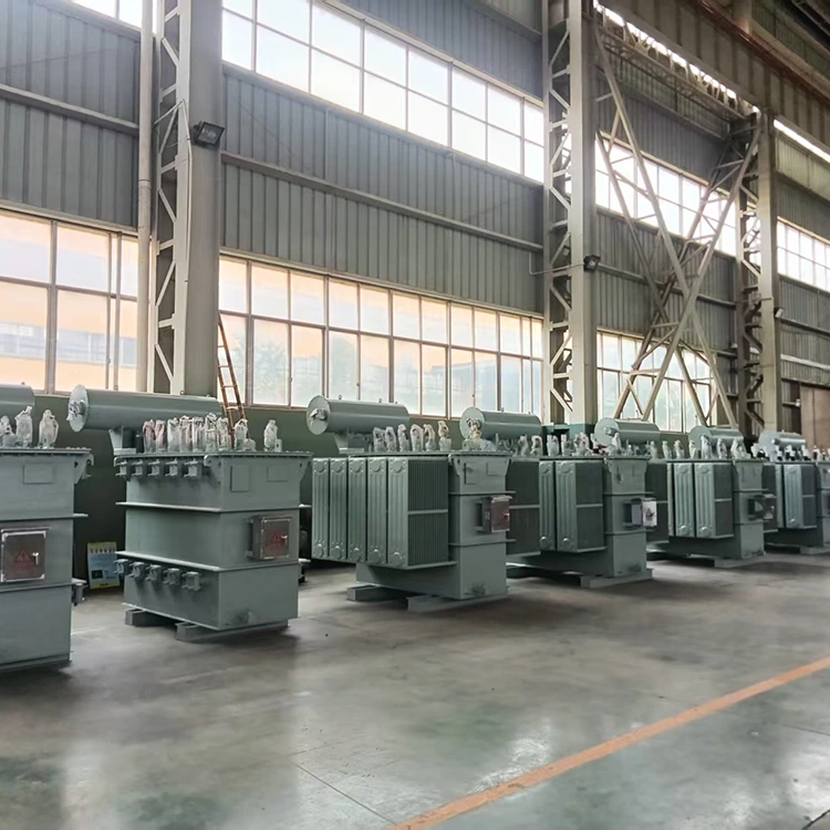
Manufacturing and Testing
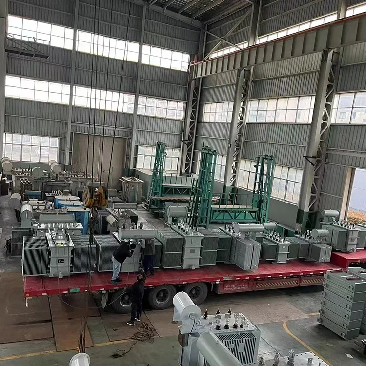
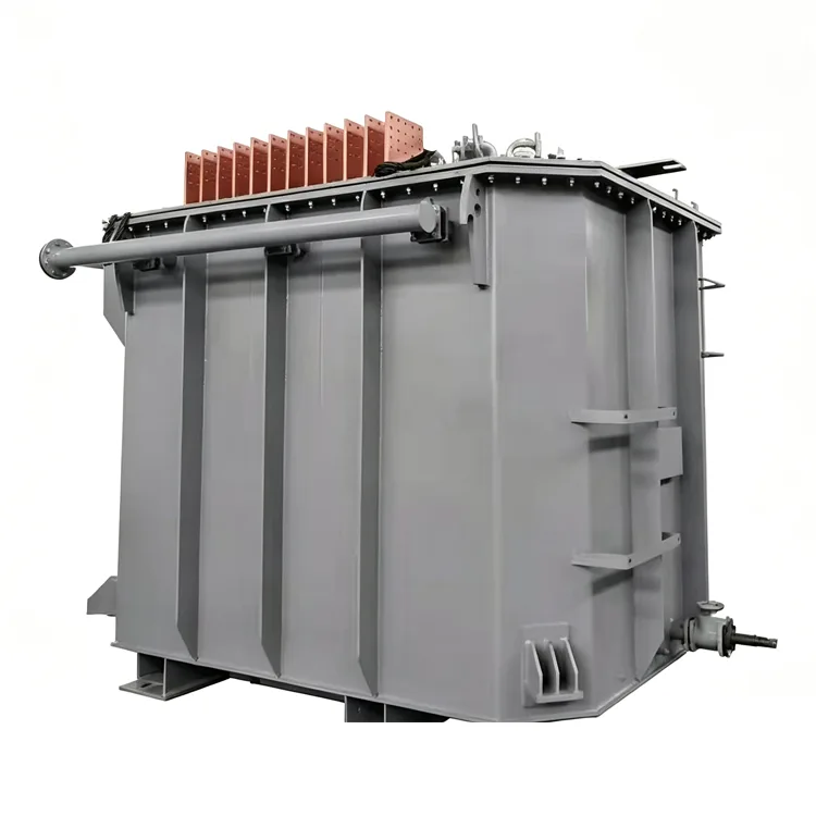
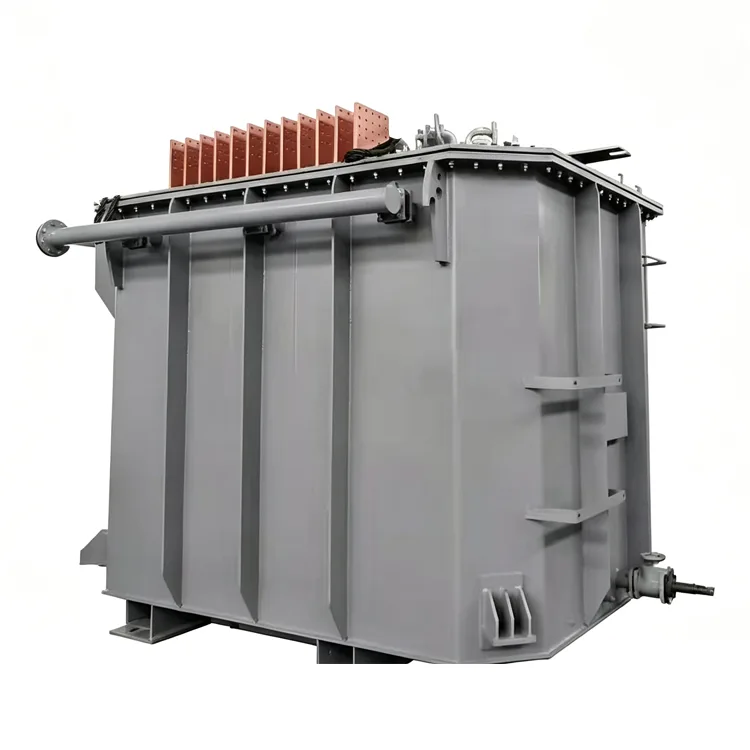
After the active part is assembled, it undergoes processing in a kerosene vapor phase vacuum drying system to remove moisture and gases from the insulation materials. For high-capacity units, transposed conductors or combined conductors are used for the windings to reduce eddy current losses. The tank and structural components are shot-blasted to remove rust and then powder-coated; large units can be equipped with radiator panels or forced-oil air-cooling systems.
In addition to routine factory tests — such as winding DC resistance, voltage ratio, insulation resistance, power-frequency withstand voltage, induced withstand voltage, no-load loss, load loss, and short-circuit impedance — temperature rise tests, lightning impulse tests, and partial discharge measurements are performed according to user requirements. Some projects also require verification data regarding the valve-side winding's ability to withstand harmonic currents.
Selection Considerations
Q: How do 6-pulse and 12-pulse rectification differ?
A 6-pulse rectifier transformer has only one set of three-phase valve-side windings, producing six pulses on the DC side after rectification. 12-pulse rectification typically requires two transformers or a single transformer with dual winding sets; a 30 ° phase shift is used to achieve 12 pulses, resulting in lower DC-side ripple and reduced harmonic content. The choice depends on the rectifier's circuit topology and grid harmonic limits.
Q: How is the valve-side voltage determined?
The valve-side voltage is calculated by the rectifier manufacturer based on the DC output voltage, rectification method, commutation angle, and transformer impedance. The transformer manufacturer designs the valve-side winding turns and insulation level according to this voltage; users are advised not to alter these specifications themselves.
Q: How does impedance affect the rectification system?
Higher impedance results in a larger commutation overlap angle and a more pronounced drop in DC output voltage under load, but it lowers the peak short-circuit current. Excessively low impedance causes the commutation process to occur too rapidly, potentially subjecting the rectifier to a high rate of change in current. The impedance range is typically specified by the designer of the rectification system.
Q: What capacity is suitable for a grid-side voltage of 35 kV?
A grid-side voltage of 35 kV is commonly found in rectifier transformers with capacities ranging from 630 kVA to 20,000 kVA. Higher-capacity units typically utilize higher voltage ratings or specialized designs. Specific specifications depend on local grid conditions and short-circuit capacity assessments.
Q: Is on-load voltage regulation supported?
Yes. High-capacity rectifier transformers are frequently equipped with on-load tap changers (OLTC) to adjust the valve-side voltage and thereby control the DC output. On-load voltage regulation affects the internal assembly layout and tank dimensions, resulting in a longer delivery lead time compared to off-circuit (no-load) tap-changing models.
Engineering Experience
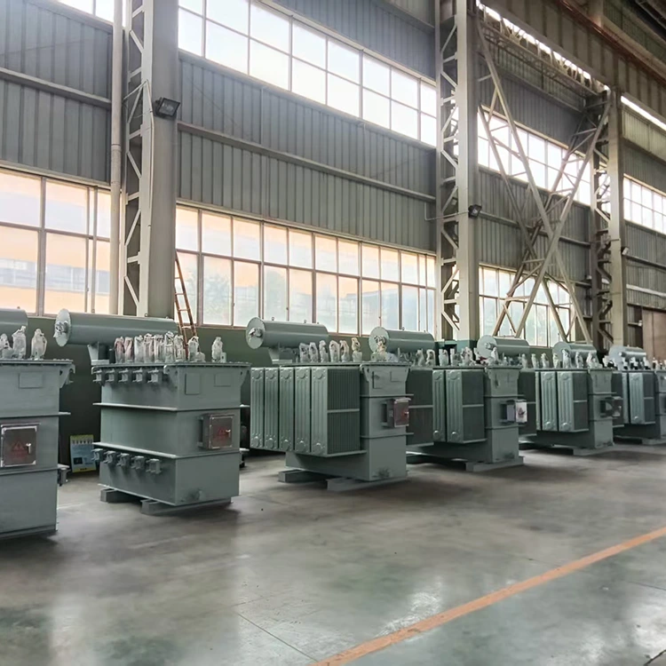
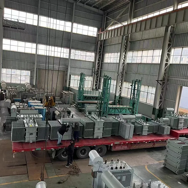
Yulan Transformer has been manufacturing electric furnace transformers and rectifier transformers since 1999, with a track record of volume supply for non-ferrous metal electrolysis, chemical electrolysis, and industrial electric heating applications. Manufacturing capabilities include an 80-ton lifting capacity, a 400 kW kerosene vapor-phase vacuum drying system, 1,200 kV impulse testing equipment, and a 400 kV partial-discharge-free power-frequency test transformer, enabling the production and testing of rectifier transformers rated at 110 kV and below.
Please contact the Yulan Transformer technical department for project-specific technical proposals, outline dimension drawings, or loss calculation reports.
Related Category
Send Inquiry
Contact Info
-
Address
No. 20, Bai'e Road, Hecun Town, Jiangshan City, Zhejiang Province,CHINA
-
Tel
-
Email
Send specs for power, furnace or rectifier transformers and get a customized quotation and price list, direct from Yulan Transformer factory. Bulk orders welcome.
News Recommendations




