
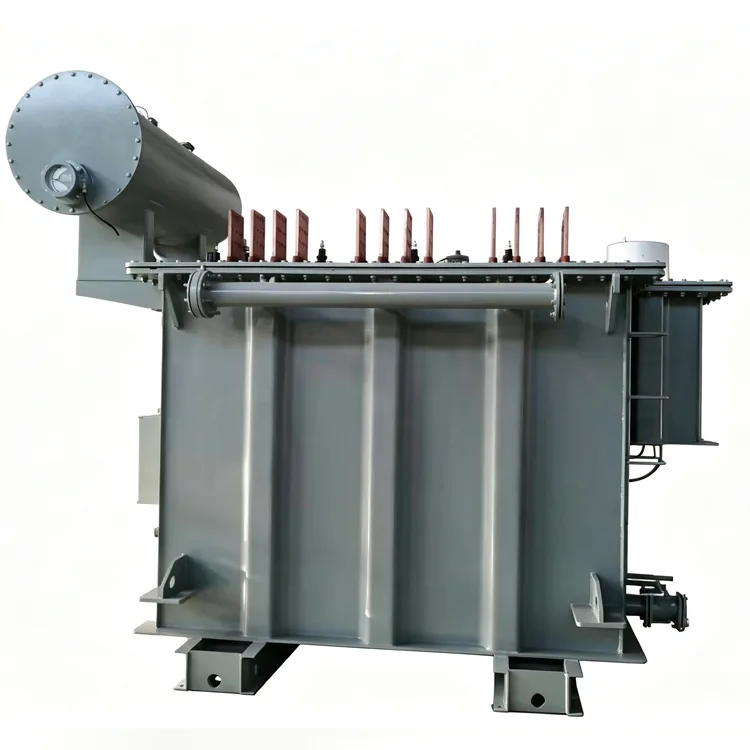
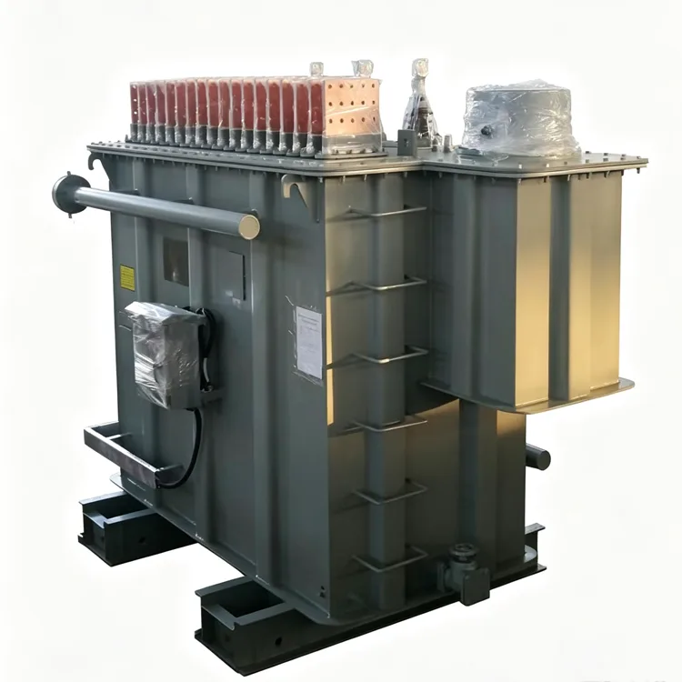
Electric Furnace Transformer for Refining
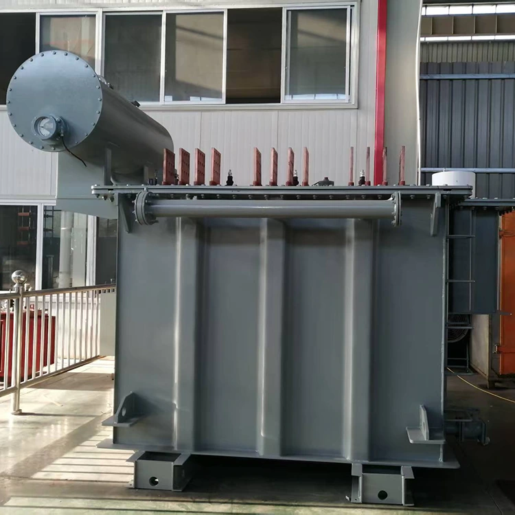
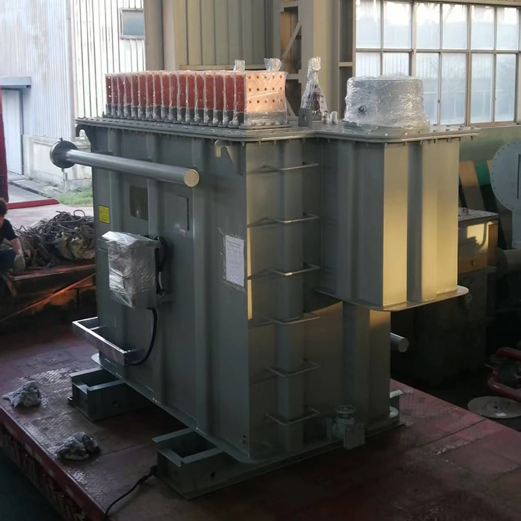
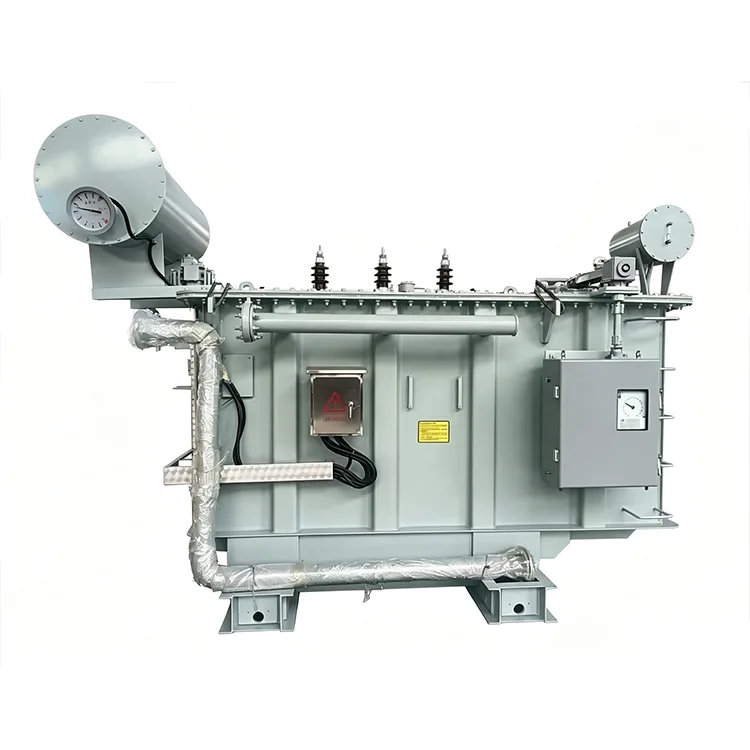
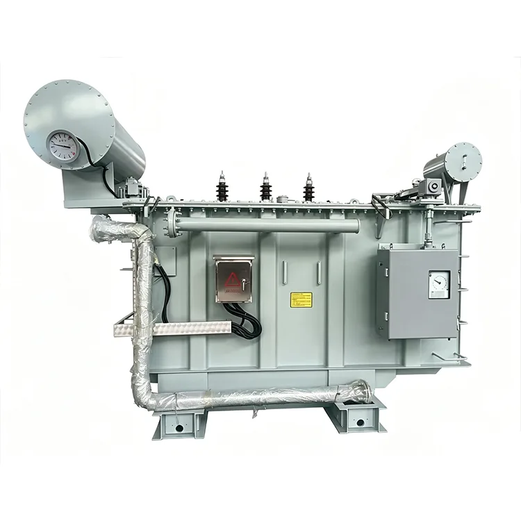
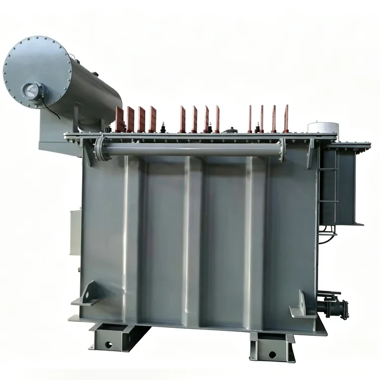
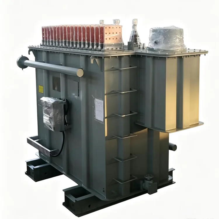
For steel refining applications, Yulan Transformer offers Electric Furnace Transformer for Refining with rated capacities ranging from 1,000 to 80,000 kVA and primary voltages spanning 6–110 kV, with customizable secondary voltages and tapping ranges. You can specify, request a quote for, or purchase the appropriate transformer equipment based on the specific requirements of the ladle and short-network system.
Refining furnaces, including ladle refining stations and vacuum degassing units, operate downstream of primary melting. The Electric Furnace Transformer for Refining supplying the refining arc must deliver precise power steps rather than absorb violent short-circuit shocks. Yulan Transformer builds electric furnace transformers for refining duty from 1000 kVA to 80,000 kVA, with primary voltages of 6 kV, 10 kV, 15 kV, 22 kV, 35 kV, or 110 kV. Secondary voltage and tap sequences are developed from the refining power curve and the short-network data provided by the steel plant.
Operating Profile
Refining arcs are shorter and more stable than melting arcs. The electrodes are typically submerged in slag, and the current swings are smaller. This reduces mechanical stress on the windings, but it increases the demand on the tap changer. Power adjustments are made frequently to control temperature and alloy recovery, so the on-load tap changer may operate dozens of times per day. The transformer must also tolerate repeated thermal cycling as heats are processed one after another.
Another difference is the interaction with the short network. The distance from the transformer secondary terminals to the electrodes introduces impedance that reduces the effective arc voltage. The transformer design must account for this voltage drop, or the refining power will fall short of the target.
Manufacturing and Verification
Yulan Transformer has produced furnace transformers since 1999, with refining furnace units operating in several steel plants. The factory is equipped with an 80-ton lifting capacity, a 400 kW kerosene vapor phase vacuum drying system, a 1,200 kV impulse test system, and a 400 kV partial discharge free power frequency test transformer. Each unit undergoes winding DC resistance, voltage ratio, insulation resistance, power frequency withstand, induced overvoltage, no-load loss, load loss, short-circuit impedance, and on-load tap changer operation tests before shipment. Test records are archived by serial number and can be traced to material batches and winding records. The company holds ISO 9001:2015, ISO 14001, and ISO 45001 certifications.
Specification Range
|
Item |
Parameter |
|
Applicable standards |
IEC 60076, GB/T 10229, JB/T 9640, customer specifications |
|
Rated capacity |
1000 kVA to 80,000 kVA |
|
Primary voltage |
6 kV, 10 kV, 15 kV, 22 kV, 35 kV, or 110 kV |
|
Secondary voltage |
120 V to 280 V, depending on ladle size and steel grade |
|
Tap range |
5 to 19 positions, commonly 8 to 13 |
|
Frequency |
50 Hz or 60 Hz |
|
Phase |
Three-phase |
|
Connection symbol |
Dd0, Yd11, D-Yd0-11, D-YdD-11, and others |
|
Short-circuit impedance |
6% to 10% at maximum secondary voltage |
|
Cooling method |
ONAN, ONAF, OFAF, or OFWF |
|
Voltage regulation |
On-load tap changing for most units; off-circuit motor drive for smaller ratings |
Typical Configurations by Ladle Size
The table below is compiled from past projects and is intended as a general guide. Final parameters are confirmed in the technical agreement.
|
Ladle size (t) |
Transformer rating (kVA) |
Primary voltage (kV) |
Secondary voltage (V) |
Taps |
Impedance (%) |
Cooling |
|
30 |
2500 |
10 |
190-120 |
5 |
7 |
ONAN |
|
60 |
5000 |
35 |
210-130 |
7 |
7.5 |
ONAF |
|
80 |
8000 |
35 |
230-140 |
9 |
8 |
ONAF |
|
120 |
12500 |
35 |
250-150 |
11 |
8.5 |
OFAF |
|
150 |
16000 |
35 |
260-160 |
13 |
9 |
OFAF |
|
200 |
25000 |
110 |
270-170 |
15 |
9.5 |
OFWF |
|
300 |
40000 |
110 |
280-180 |
17 |
10 |
OFWF |
Design Notes
Short-network voltage drop
The Electric Furnace Transformer for Refining secondary voltage must be set high enough to compensate for the cable and busbar drop between the transformer and the electrodes. The customer should provide the short-network impedance and length so the winding design can be adjusted accordingly.
Tap changer selection
Refining duty requires frequent tap changes. Standard power transformer tap changers may not reach the expected contact life. Vacuum-type on-load tap changers or units specifically rated for furnace duty are preferred. A separate oil filtering system for the tap changer compartment is also recommended.
Winding construction
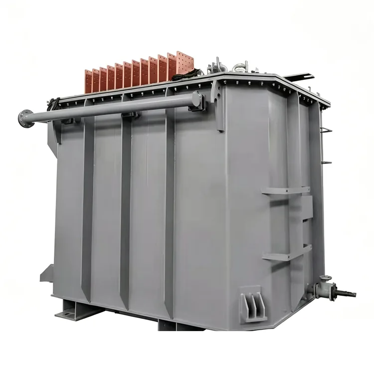
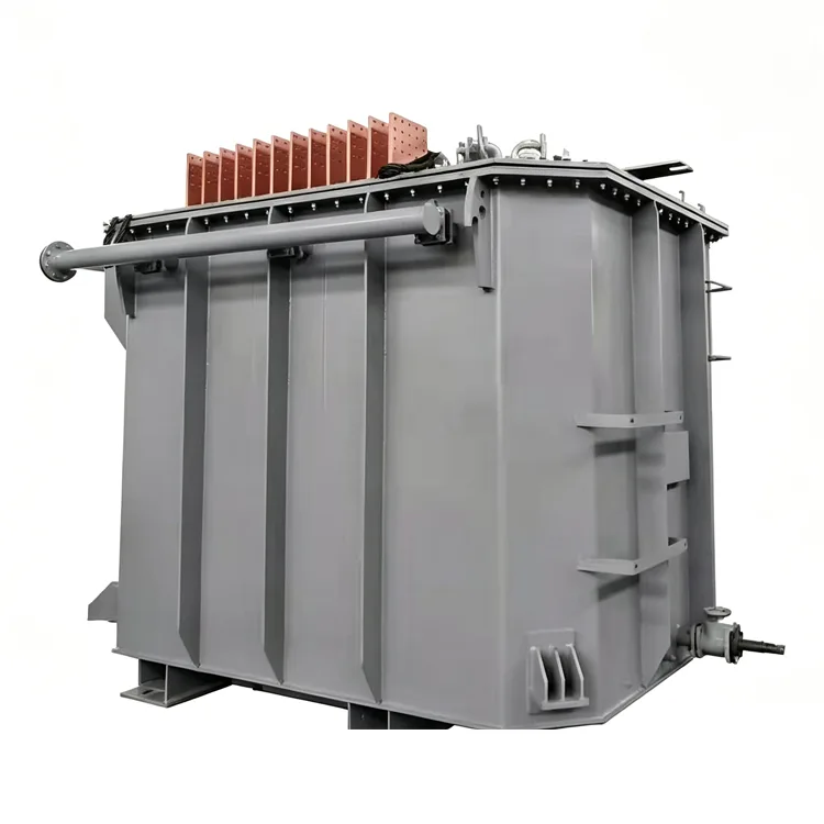
Secondary currents are high, so transposed conductors or multiple parallel branches are used. End transpositions keep current distribution even. The leads are made from copper bars arranged for same-phase inverse parallel connection where possible, reducing external magnetic fields and structural heating.
Thermal cycling
Batch operation causes repeated heating and cooling. The clamping structure uses pre-stressed tie rods and spring-loaded pressure plates to maintain winding pressure without damaging insulation. Top-oil temperature rise is verified under continuous full-load conditions, not short-time overload assumptions.
Harmonics and reactive power
The refining arc produces harmonic currents and a lagging power factor, typically between 0.75 and 0.85. Conductor cross-sections and shielding include margin for harmonic losses. Reactive power compensation is handled at the system level.
Frequently Asked Questions
Can a refining furnace transformer be used for primary melting?
It is not recommended. Melting furnace transformers are designed for higher impedance and more severe short-circuit forces. A refining transformer may not survive the frequent near-short-circuit events of scrap melting. The reverse direction, using a melting transformer for refining, is sometimes possible but the tap range and voltage steps may not match the refining process.
How is the secondary voltage range determined?
The furnace builder provides the voltage curve based on ladle size, electrode diameter, and steel grade. The transformer designer converts this into turns and tap positions. Changing the secondary voltage after design approval requires reworking the winding.
Is water cooling necessary for refining furnace transformers?
Below approximately 8000 kVA, air cooling is usually sufficient. Above that rating, or when space is limited, water cooling reduces cooler size but requires more maintenance. Oil pressure must always exceed water pressure to prevent water ingress.
How many tap positions are suitable?
For plain carbon steel, 5 to 8 taps are enough. Alloy and stainless steels often need 11 to 15 taps for finer temperature control. More taps increase tap changer cost and add potential failure points, so the number should match the process requirement.
What site conditions affect installation?
Refining areas have high ambient temperature and dust. The transformer should be placed in a well-ventilated location away from slag splashing. Outdoor installations need weatherproof terminal boxes and control cabinets. High ambient temperature reduces cooling capacity, so the cooler rating must be adjusted accordingly.
Related Category
Send Inquiry
Contact Info
-
Address
No. 20, Bai'e Road, Hecun Town, Jiangshan City, Zhejiang Province,CHINA
-
Tel
-
Email
Send specs for power, furnace or rectifier transformers and get a customized quotation and price list, direct from Yulan Transformer factory. Bulk orders welcome.
News Recommendations




