
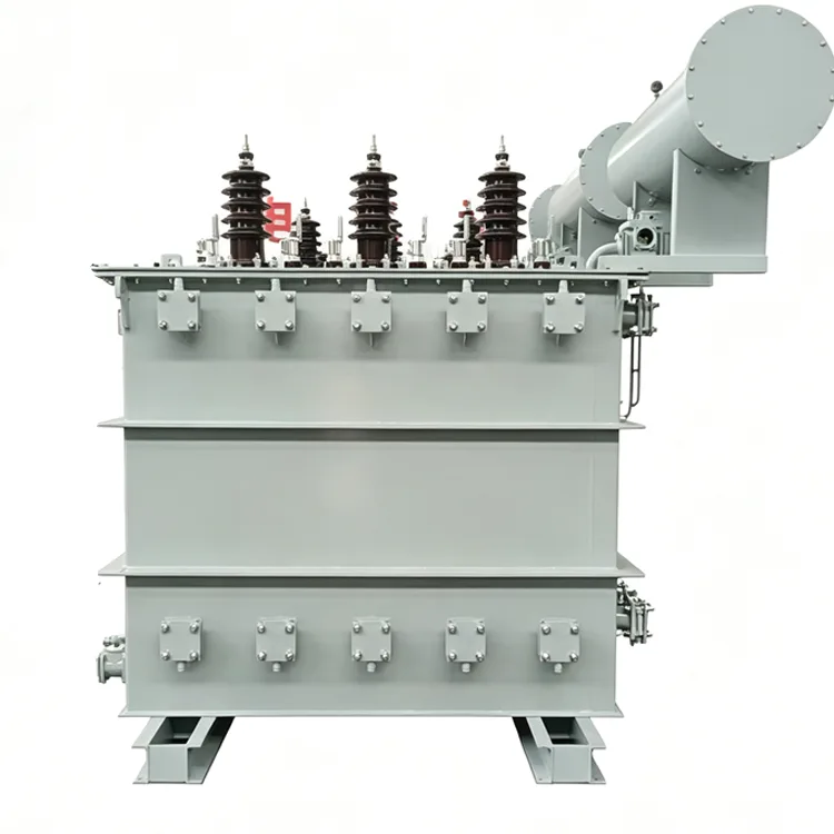
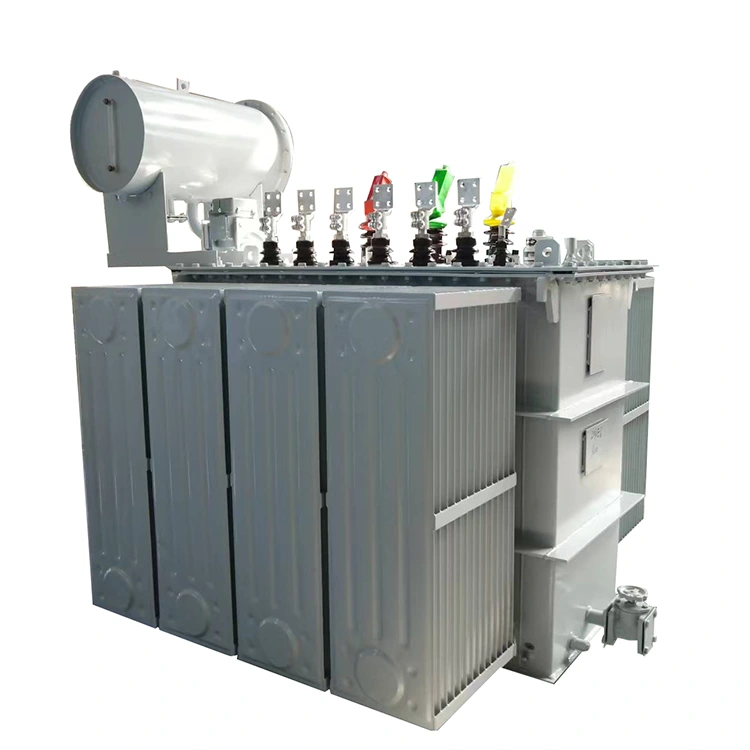
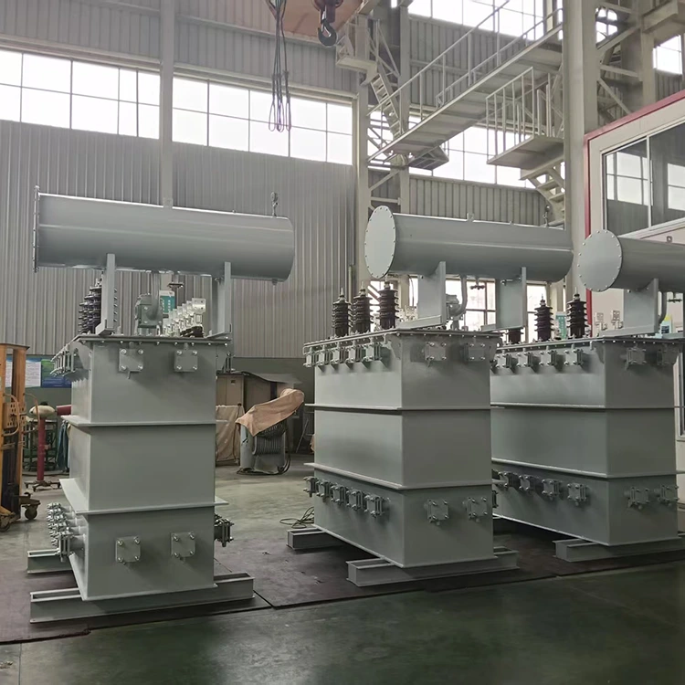
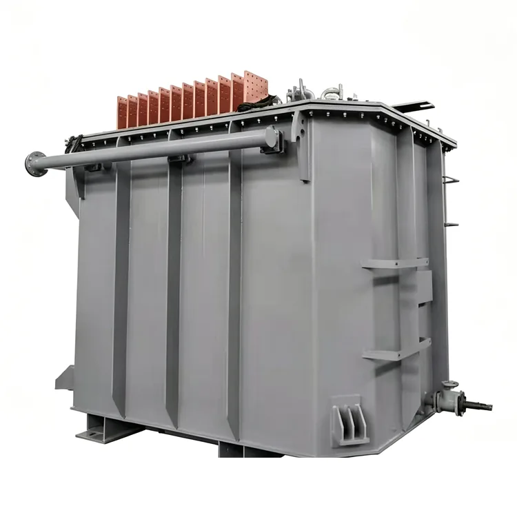
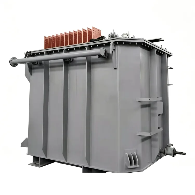
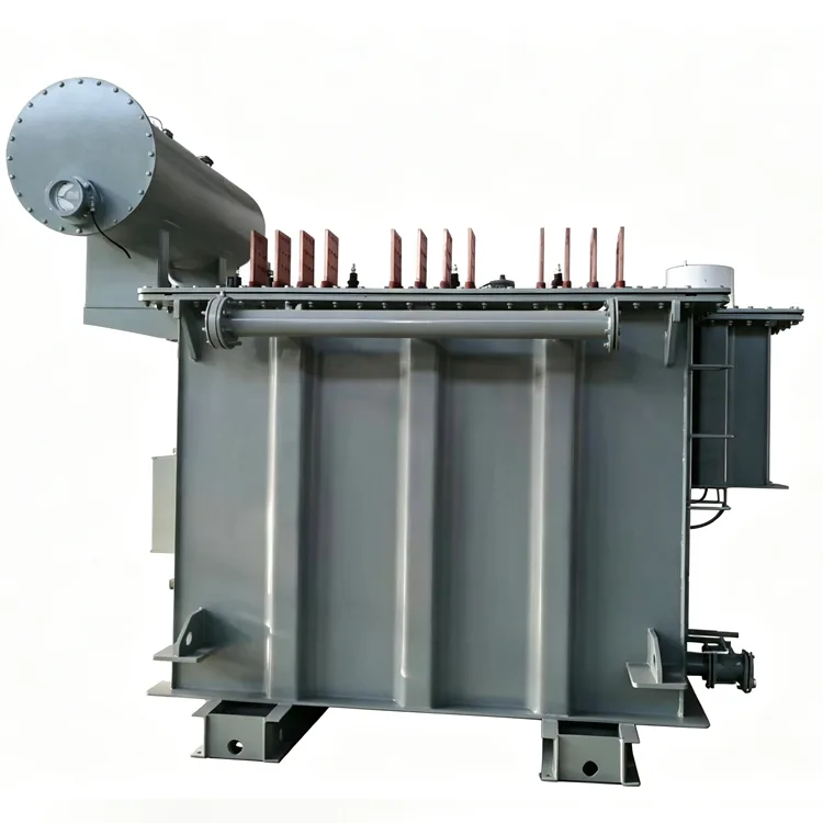
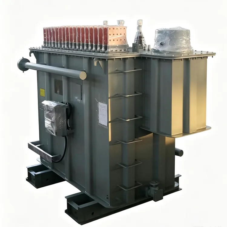
Industrial 12-Pulse Power Rectifier Transformer
Rectifier transformers operating in industrial environments are subject to harmonic-rich load currents and frequent load variations. A 12-pulse configuration reduces the presence of 5th and 7th harmonics on the primary side by introducing a 30° phase shift between two rectifier bridges. Yulan Transformer builds Industrial 12-Pulse Power Rectifier Transformers from 630 kVA up to 80,000 kVA, with primary voltages of 6 kV, 10 kV, 15 kV, 22 kV, or 35 kV. Secondary parameters are determined individually for each rectifier circuit.
Why 12-Pulse Instead of 6-Pulse
A 6-pulse rectifier draws significant 5th and 7th harmonic currents from the supply. These harmonics increase winding losses, cause voltage distortion, and often require external filtering. A 12-pulse system uses two 6-pulse bridges fed by phase-shifted voltages. When the phase shift is 30°, the 5th and 7th harmonic currents cancel on the primary side. The remaining dominant harmonics are the 11th and 13th, which are easier to manage and have lower amplitudes.
This approach is common in industrial plants where harmonic limits are specified by IEEE 519 or similar grid codes. It is also used when the rectifier load is large enough that harmonic filters alone would be costly.
System Configurations
Industrial 12-Pulse Power Rectifier Transformers are supplied in two main arrangements.
Two Separate Transformers
Two 6-pulse transformers are built with +15° and -15° phase shifts. Each feeds one rectifier bridge. This arrangement allows one unit to be taken out of service for maintenance while the other continues operating at reduced load. It also simplifies transport for very large ratings.
Single Transformer with Dual Secondary Windings
One transformer contains two valve-side windings, one connected in wye and one in delta. The natural 30° phase difference creates the 12-pulse effect. This design saves floor space and reduces the number of primary switchgear connections, but a single failure affects the entire rectifier system.
Both configurations provide comparable harmonic cancellation. The choice depends on site layout, maintenance strategy, and redundancy requirements.
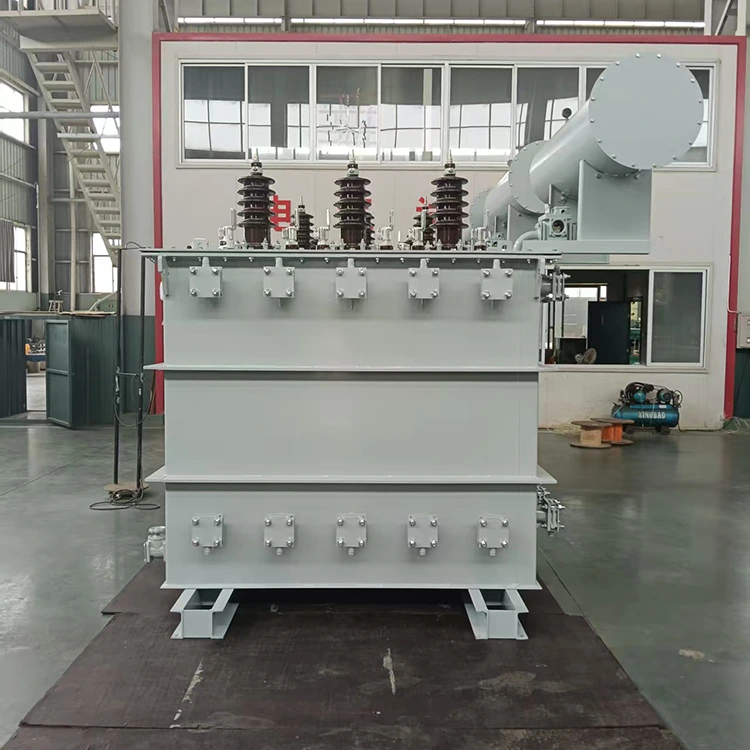
Typical Industrial Applications
● Aluminum, copper, and zinc electrolysis plants
● Chlor-alkali electrolysis in chemical facilities
● DC arc furnaces and submerged arc furnaces
● Large electroplating and anodizing lines
● Traction power supply for urban rail systems
● Industrial DC drives with high power ratings
Technical Specifications
|
Item |
Parameter |
|
Applicable standards |
IEC, GB, ANSI/IEEE, NEMA, and industry-specific specifications |
|
Rated capacity |
630 kVA to 80,000 kVA |
|
Primary rated voltage |
6 kV, 10 kV, 15 kV, 22 kV, or 35 kV |
|
Secondary voltage |
Determined by the rectifier circuit, commonly 380 V to 3000 V |
|
Rated frequency |
50 Hz or 60 Hz |
|
Phase |
Three-phase |
|
Phase shift |
±15°, 0°/30°, or as required by the system |
|
Primary connection |
Delta or wye |
|
Secondary connection |
Wye, delta, or dual windings |
|
Short-circuit impedance |
6% to 12% or as specified by the rectifier designer |
|
Cooling method |
ONAN, ONAF, or OFWF |
|
Voltage regulation |
Off-circuit or on-load tap changing |
Phase Shift Accuracy
The phase shift is produced by extended delta or zigzag winding connections. The number of turns in the phase-shifting winding must be calculated precisely. If the phase angle deviates from the design value, circulating currents appear between the two rectifier bridges. This reduces the cancellation of 5th and 7th harmonics and increases losses.
During production, Yulan Transformer verifies the turn count of phase-shifting windings and measures the actual phase angle during factory testing. The measured value is recorded in the test report. Typical phase angle tolerance is within ±0.5°.
For two-transformer arrangements, the short-circuit impedance of both units must be kept close. A large impedance difference causes uneven load sharing and weakens the harmonic cancellation effect.
Losses and Temperature Rise
A 12-pulse rectifier transformer eliminates most 5th and 7th harmonic currents, so additional winding losses are lower than in a 6-pulse design. However, 11th and 13th harmonics remain, and the design still includes margin for eddy current losses.
The core operates at a flux density lower than that of a standard distribution transformer. This avoids saturation caused by possible DC components during transient conditions. Temperature rise is verified under the specified harmonic current spectrum, not just under sinusoidal current.
Construction Features
Windings
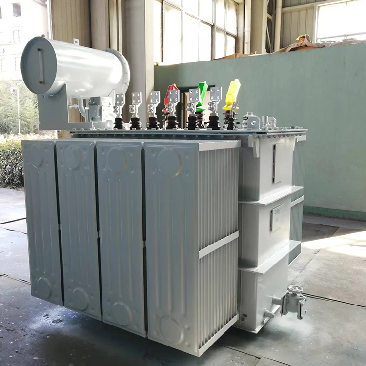
Valve-side currents in industrial rectifier applications often reach several thousand amperes. Large units use transposed conductors or multiple parallel conductors. Transpositions at the winding ends help equalize current distribution and reduce circulating losses.
Lead Arrangement
Secondary leads are usually made from copper bars. The arrangement considers proximity effects and mechanical support. Multiple secondary bushings or terminal boards are common.
Tank Shielding
Harmonic flux induces eddy currents in the tank walls and clamping structures. Magnetic shields or electromagnetic shields are installed on the tank inner surface for larger ratings. This reduces stray losses and prevents local overheating.
Tap Changer
On-load tap changing is frequently used in rectifier service to adjust the secondary voltage and control DC output. The tap changer increases the complexity of the active part and requires additional space inside the tank.
Factory Testing
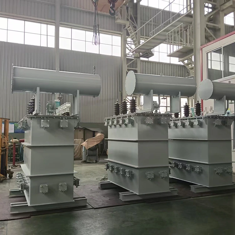
Routine tests include winding DC resistance, voltage ratio, insulation resistance, power frequency withstand, induced overvoltage, no-load loss, load loss, and short-circuit impedance. Additional tests for 12-pulse rectifier transformers include phase angle measurement, insulation testing between valve-side windings, and partial discharge measurement.
For primary voltages of 35 kV or higher, lightning impulse tests are performed according to applicable standards. Temperature rise tests under harmonic current conditions can be arranged when specified by the purchaser. Test records are archived by serial number and can be traced to winding and core assembly processes.
FAQ
Which is better for a new installation: one dual-secondary transformer or two separate transformers?
For smaller ratings, a single transformer with dual secondary windings is usually more economical and requires less floor space. For larger ratings or when maintenance flexibility is important, two separate transformers are preferred. The final decision should also consider transport limits and the availability of spare units.
Does a 12-pulse system completely eliminate harmonics?
No. The 5th and 7th harmonics are largely canceled, but the 11th and 13th remain. In practice, some residual 5th and 7th components may still appear due to phase angle error or unbalanced loads. Additional passive or active filters may be required for strict harmonic limits.
Can a 6-pulse installation be upgraded to 12-pulse?
Generally no. The phase shift must be built into the transformer windings. Retrofitting would require replacing the transformer or adding a separate phase-shifting transformer. The second option may be possible in some cases but needs careful evaluation of impedance matching and space.
How is the secondary voltage determined?
The rectifier manufacturer calculates the required valve-side voltage based on the DC output voltage, rectifier circuit, commutation overlap, and transformer impedance. The transformer manufacturer then designs the secondary winding to match this voltage. Changing the secondary voltage after design approval can affect the entire winding layout.
What protection is recommended for 12-pulse rectifier transformers?
Standard overcurrent protection may misoperate because of harmonic currents. Protective relays should include harmonic restraint or be selected specifically for rectifier duty. Temperature monitoring, gas relays, oil level indicators, and pressure relief devices are recommended for the transformer itself. For large units, continuous monitoring of winding temperature and oil condition is advisable.
Manufacturing Capability
Yulan Transformer has produced furnace transformers and rectifier transformers since 1999. The company operates under 110 kV class production and testing conditions, including an 80-ton lifting capacity, a 400 kW kerosene vapor phase vacuum drying system, a 1,200 kV impulse test system, and a 400 kV partial discharge free power frequency test transformer. These facilities support the insulation processing and factory verification of large industrial rectifier transformers.
For project-specific phase shift schemes, loss calculations, or outline drawings, please contact the Yulan Transformer technical department.
Related Category
Send Inquiry
Contact Info
-
Address
No. 20, Bai'e Road, Hecun Town, Jiangshan City, Zhejiang Province,CHINA
-
Tel
-
Email
Send specs for power, furnace or rectifier transformers and get a customized quotation and price list, direct from Yulan Transformer factory. Bulk orders welcome.
News Recommendations




