
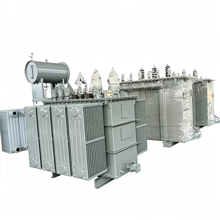
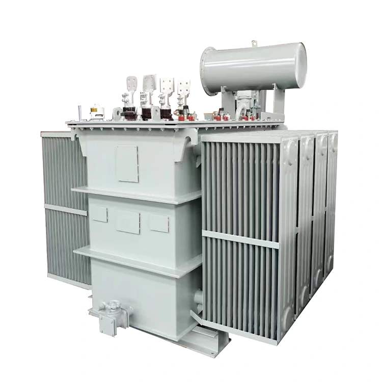
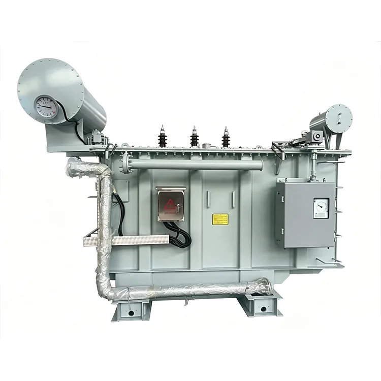
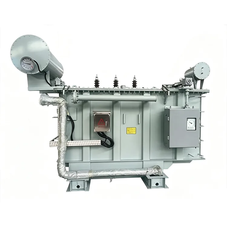
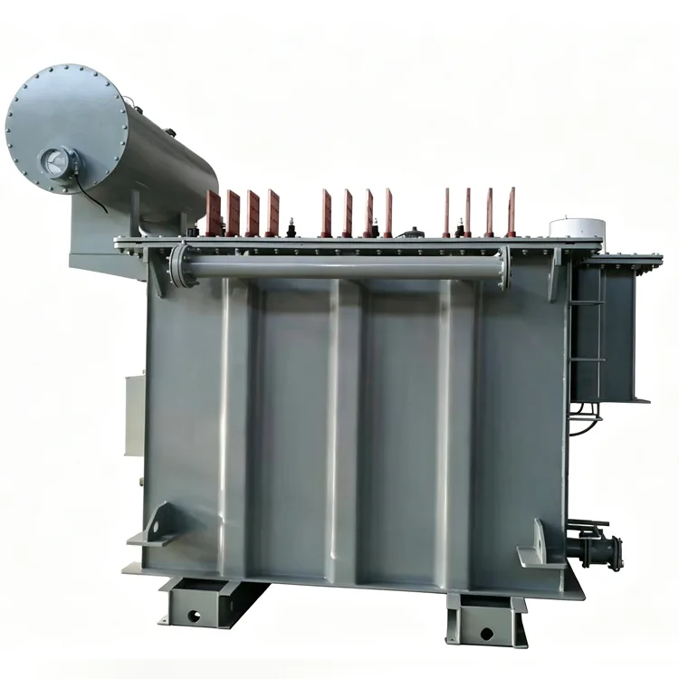
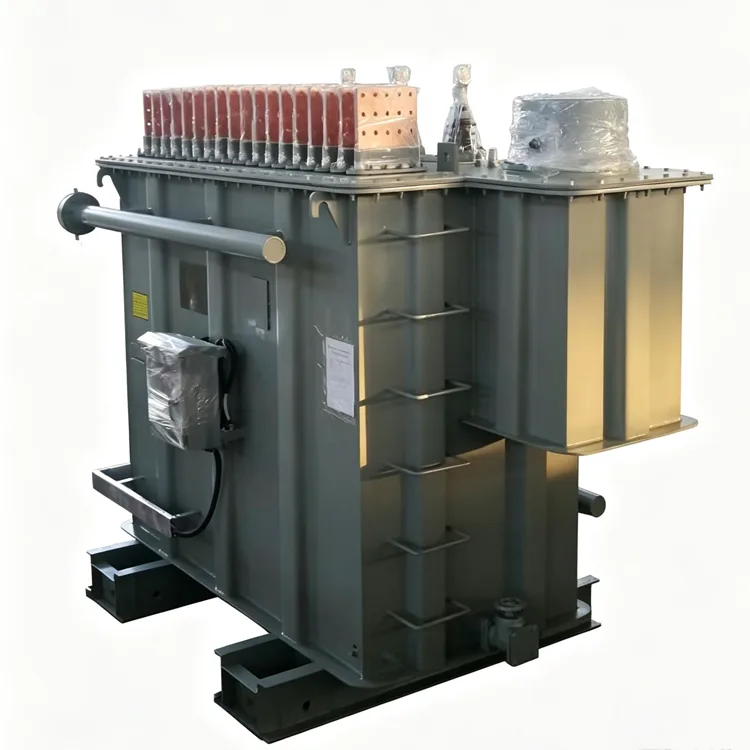
Industrial 6-Pulse Power Rectifier Transformer
In applications such as electrolysis, electroplating, graphitization, and DC drive systems, power transformers are required to supply power directly to rectifiers. Since rectifier loads produce non-sinusoidal current waveforms with high harmonic content, the transformer windings and core must be designed specifically for these operating conditions, rather than relying on the standard parameters used for conventional distribution transformers. Yulan Transformer’s Industrial 6-Pulse Power Rectifier Transformers range from 630 kVA to 80,000 kVA; primary (grid-side) voltage ratings include 6 kV, 10 kV, 15 kV, 22 kV, and 35 kV, while secondary (valve-side) parameters are calculated individually based on the specific rectifier circuit and DC output requirements.
The primary stress experienced by rectifier transformers during operation stems from harmonic currents. 6-pulse rectifier circuits generate characteristic harmonics — such as the 5th, 7th, 11th, and 13th — on the grid side, causing additional losses in winding conductors and structural components. If adequate margins for current density and heat dissipation are not incorporated during the design phase, localized temperature rises may exceed the limits of the insulation system.
Furthermore, certain rectifier circuits can induce DC magnetic bias in the core during transient processes, leading to a shift in magnetic flux density. Consequently, the operating magnetic flux density in rectifier transformer cores is typically set lower than that of distribution transformers of equivalent capacity to prevent increased noise levels and elevated no-load losses.
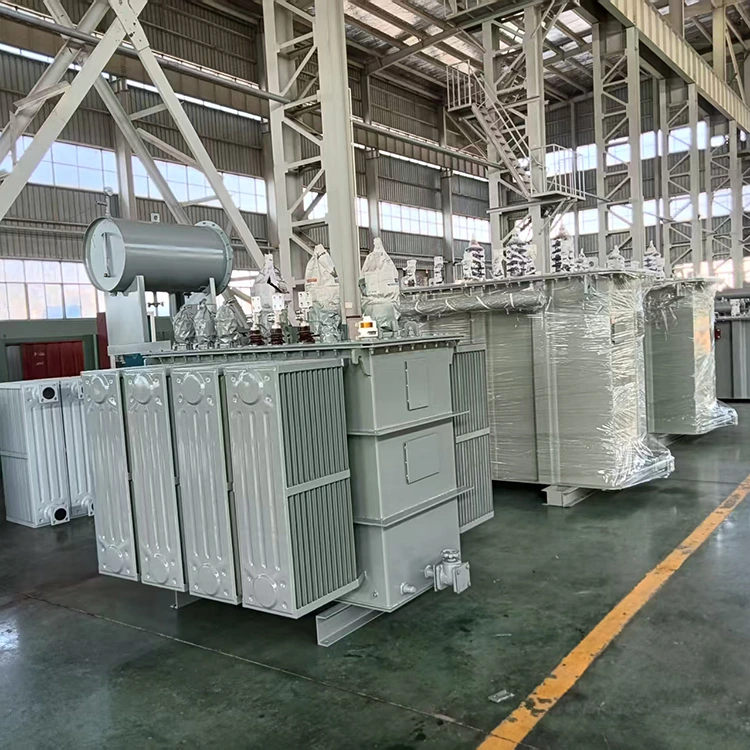
Installation Scenarios
Industrial 6-Pulse Power Rectifier Transformer s are commonly used in the following applications:
● Non-ferrous metal electrolysis workshops (e.g., aluminum, copper, and zinc electrolytic cells)
● Electroplating production lines and anodizing equipment
● Graphitization furnaces and industrial resistance furnaces
● DC traction power supply systems for urban rail transit
● Chlor-alkali electrolytic cells in the chemical industry
● Power supplies for DC electric arc furnaces and submerged arc furnaces
These applications impose varying requirements regarding short-circuit impedance, valve-side voltage regulation ranges, and overload capabilities; therefore, transformer specifications must be matched with the parameters provided by the rectifier manufacturer. Key Specifications
Item Parameter
|
Item |
Standards |
|
Executive Standard |
IEC, GB, ANSI/IEEE, NEMA, and industry-specific specifications |
|
Rated Capacity |
630 kVA to 80,000 kVA |
|
Grid-side Rated Voltage |
6 kV, 10 kV, 15 kV, 22 kV, 35 kV |
|
Valve-side Rated Voltage |
Determined by the rectifier circuit; common range: 380 V to 3,000 V |
|
Rated Frequency |
50 Hz / 60 Hz |
|
Number of Phases |
Three-phase |
|
Grid-side Connection |
D or Y, per system requirements |
|
Valve-side Connection |
y, d, or dual-winding |
|
Short-circuit Impedance |
6% to 12% or per rectifier requirements |
|
Cooling Method |
ONAN, ONAF, OFWF |
|
Voltage Regulation Method |
Off-circuit tap changing or on-load tap changing |
Design Differences
Compared to distribution transformers, Industrial 6-Pulse Power Rectifier Transformer s exhibit significant differences in the following areas:
Winding Conductors
Valve-side currents often reach several thousand amperes, making it difficult for a single conductor to meet current-carrying requirements. High-capacity units utilize transposed conductors or multiple parallel conductors, incorporating transposition structures at the winding ends to ensure uniform current distribution across parallel branches and minimize circulating current losses.
Lead Arrangement
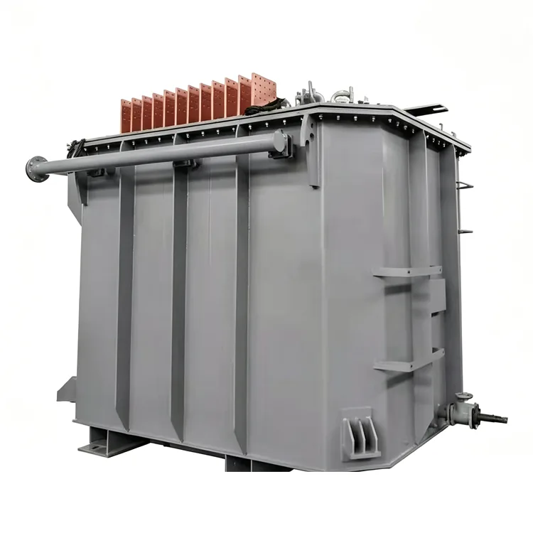
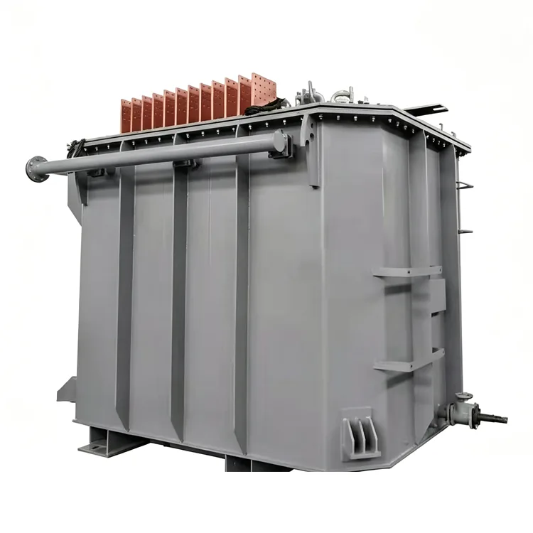
Due to the high number of valve-side output terminals and high current levels, lead arrangements must account for proximity effects and mechanical support. Some units employ direct copper busbar connections to reduce contact resistance and localized heating.
Tank and Shielding
Harmonic magnetic fields induce eddy currents in the tank walls and clamping structures. High-capacity rectifier transformers often feature magnetic or electric shielding on the inner tank walls to reduce stray losses and prevent localized overheating.
Impedance Selection
Short-circuit impedance is not a fixed value; it must be coordinated with the rectifier's commutation reactance. Excessively high impedance increases DC voltage regulation and reduces rectification efficiency, while excessively low impedance leads to excessive short-circuit currents, compromising equipment safety. Typically, the rectifier system designer specifies the impedance range, and the transformer manufacturer optimizes the winding structure within that range. Production and Verification
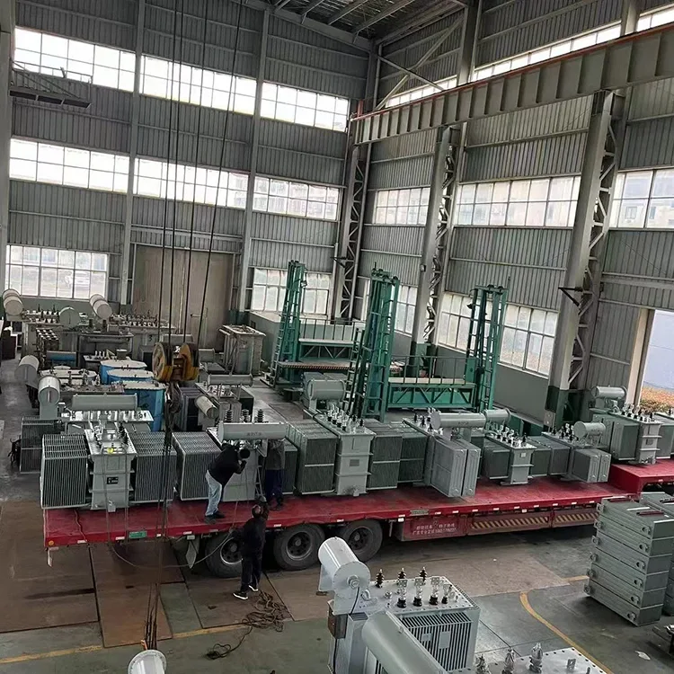
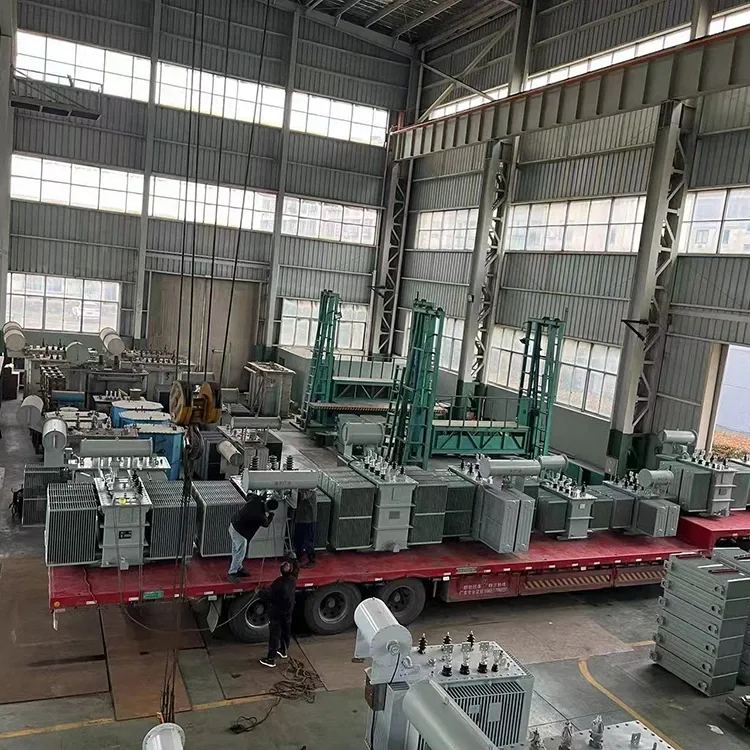
After the active part is assembled, it undergoes a kerosene vapor phase vacuum drying process to remove moisture and gases from the insulation materials. For products rated at 35 kV and above, factory acceptance tests include lightning impulse tests and partial discharge measurements. Rectifier transformers also undergo temperature rise tests based on customer requirements to verify that the hot-spot temperature rise under rated harmonic currents complies with insulation class standards.
The company holds ISO 9001:2015, ISO 14001, and ISO 45001 certifications. Test data is archived by product serial number, ensuring traceability back to key manufacturing stages such as winding, core stacking, and drying of the active part.
Selection Reference
Q: What is the maximum capacity for a 35 kV grid-side voltage?
A 35 kV grid-side voltage typically corresponds to a capacity range of 630 kVA to 20,000 kVA. Higher-capacity units may require higher voltage ratings or special structural designs; assessment should consider local grid short-circuit capacity and substation layout constraints.
Q: Is phase shifting required for the valve-side winding?
A 6-pulse rectifier configuration does not inherently require phase shifting; the valve-side winding outputs three-phase AC directly to the rectifier bridge. If grid harmonic limits are strict, 12-pulse or 24-pulse schemes may be used, requiring phase-shifting windings (common phase-shift angles include ± 7.5 ° and ± 15 ° ).
Q: Can they operate in parallel?
Yes, but parallel operation requires transformers to have identical vector groups, similar short-circuit impedances, and a capacity ratio not exceeding 3:1. For rectifier loads, phase alignment of the valve-side voltage is also critical to prevent circulating currents.
Q: What is the function of on-load tap changing (OLTC) in a rectifier system?
OLTC allows for valve-side voltage adjustment — and consequently DC output adjustment — without interrupting power. For electrolytic loads, OLTC helps maintain stable DC current despite grid voltage fluctuations. OLTC increases the complexity of the active part and the size of the tank; space for the tap changer must be allocated during the design phase.
Q: Do rectifier transformers require special protection configurations?
Yes. Due to high harmonic content, conventional overcurrent protection may malfunction; therefore, harmonic restraint or specialized protection devices are typically required. The transformer unit should be equipped with temperature monitoring and pressure relief devices; for high-capacity units, the installation of a gas relay and an oil level gauge is recommended.
Technical Capabilities
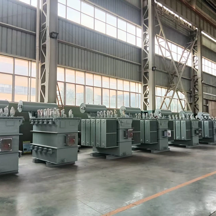
Yulan Transformer has been manufacturing electric furnace transformers and rectifier transformers since 1999 and possesses the capabilities to manufacture and test products rated at 110kV and below. Key equipment includes an 80-ton lifting system, a 400kW kerosene vapor phase vacuum drying system, 1200kV impulse testing equipment, and a 400kV partial-discharge-free power-frequency test transformer, enabling the company to meet the insulation processing and testing requirements for high-capacity rectifier transformers.
Please contact Yulan Transformer ’ s technical department for project-specific technical proposals, loss calculations, or outline drawings.
Related Category
Send Inquiry
Contact Info
-
Address
No. 20, Bai'e Road, Hecun Town, Jiangshan City, Zhejiang Province,CHINA
-
Tel
-
Email
Send specs for power, furnace or rectifier transformers and get a customized quotation and price list, direct from Yulan Transformer factory. Bulk orders welcome.
News Recommendations




