
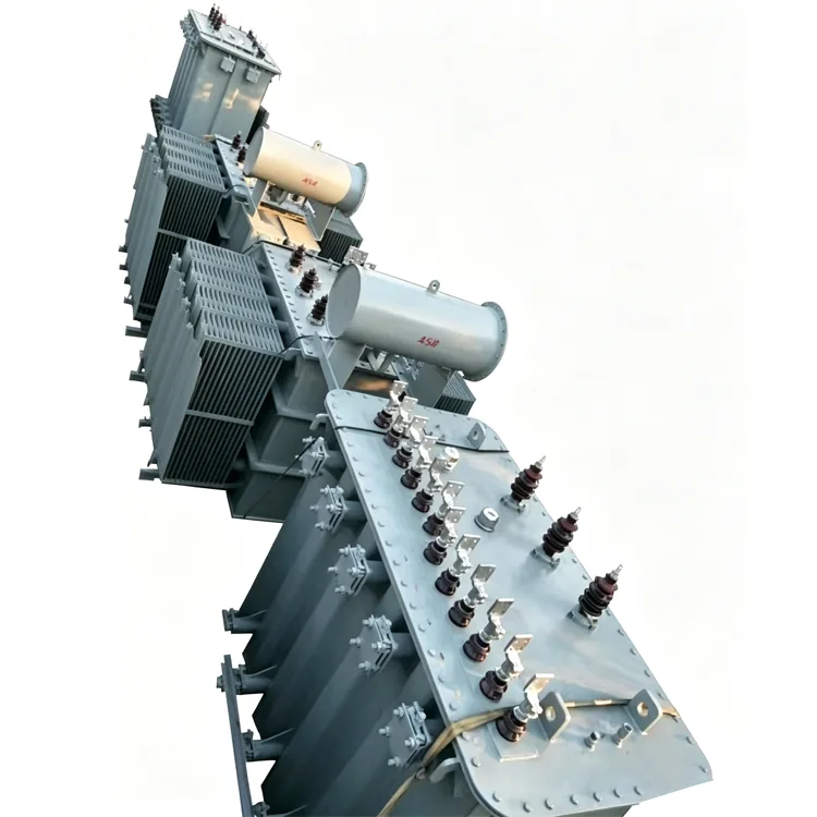
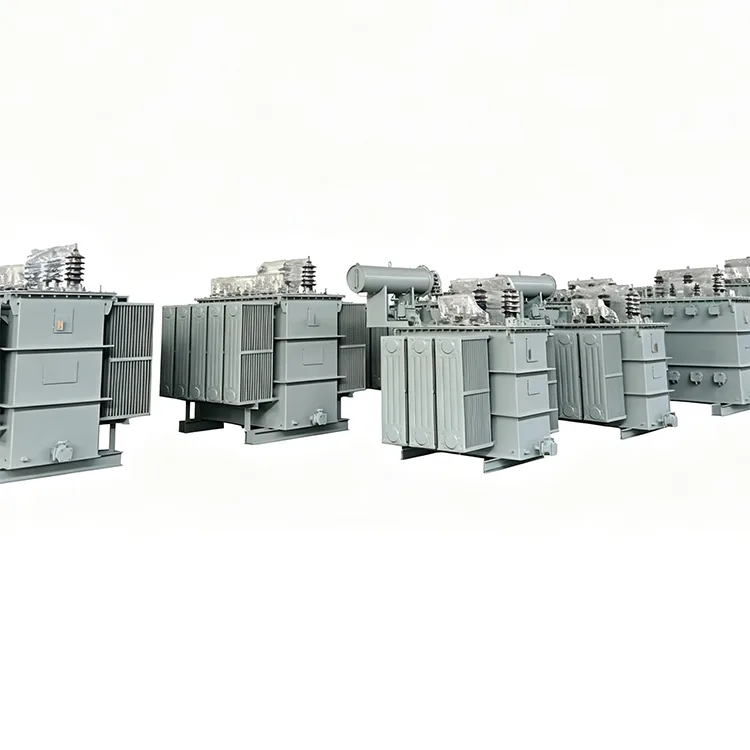
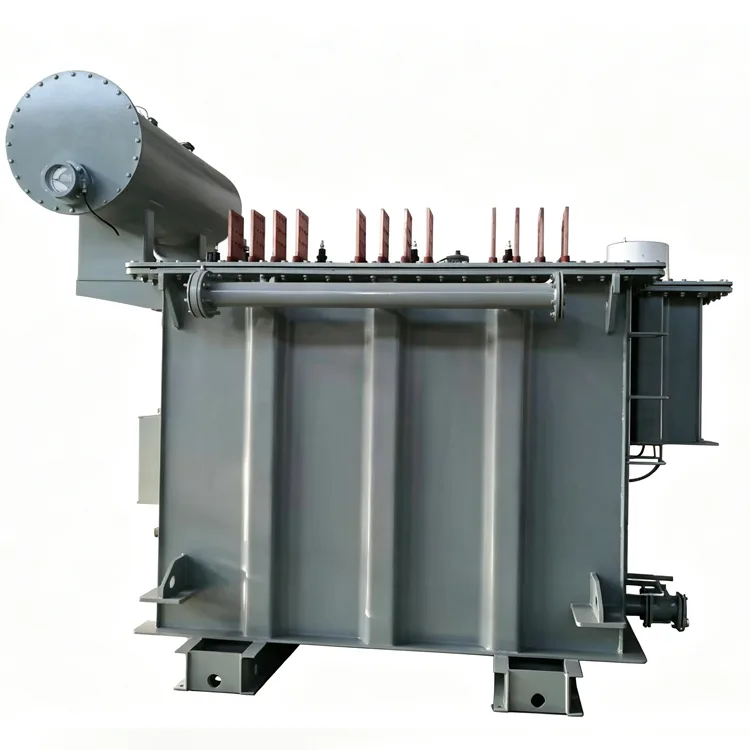
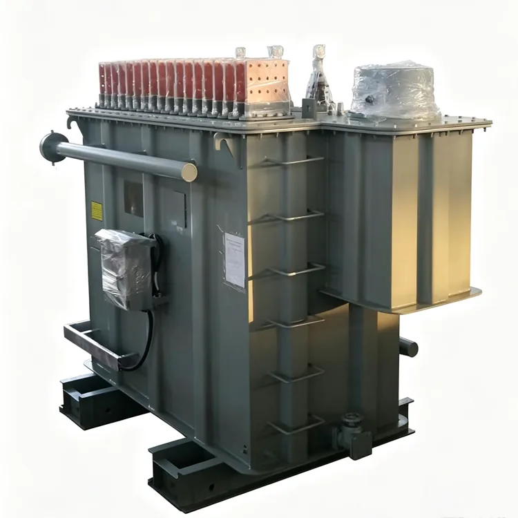
Multi-split Rectifier Transformer
Yulan Transformer supplies Multi-split Rectifier Transformers from 630 kVA to 80,000 kVA for high-current electrolysis, electroplating, graphitization, and DC power systems. Customize split configurations and voltage ratings, request a quote, or source reliable transformer solutions for industrial projects.
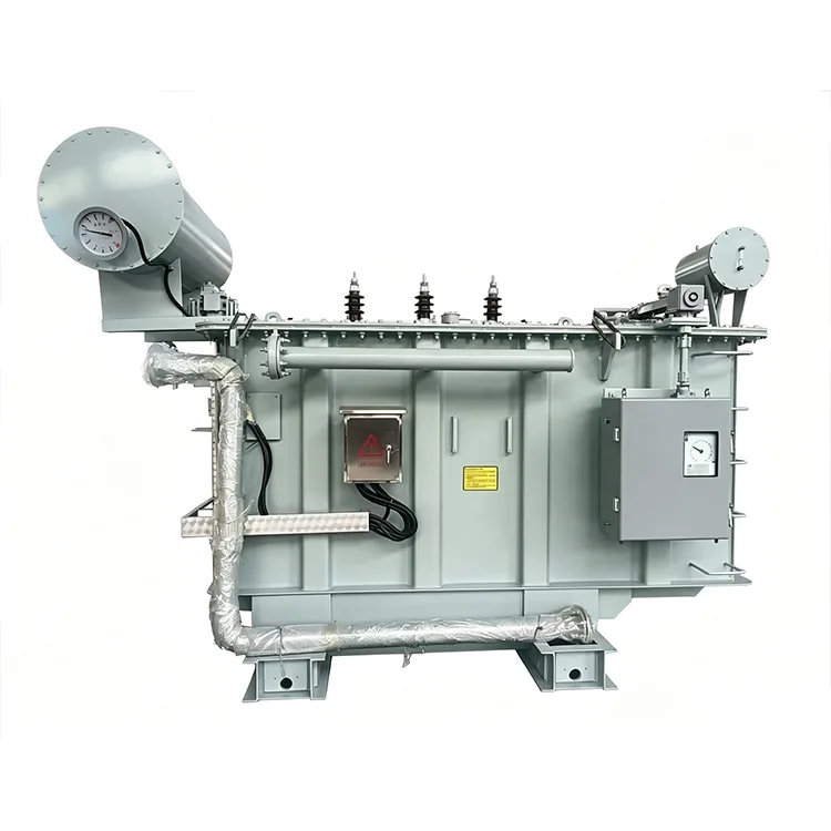
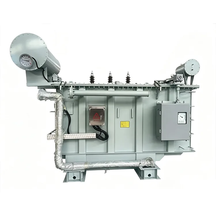
In systems for electrolysis, electroplating, and large-scale DC drives, the DC current on the valve side can reach tens of thousands of amperes. Using a single-path valve-side winding results in an excessively large conductor cross-section, making winding and terminal lead-out difficult, while also increasing the risk of localized overheating as current rises. Multi-split rectifier transformers divide the valve-side winding into several independent branches, each supplying a different rectifier bridge; this reduces the current per branch and enhances system operational flexibility. Yulan Transformer manufactures multi-split rectifier transformers with capacities ranging from 630 kVA to 80,000 kVA and grid-side voltage ratings of 6 kV, 10 kV, 15 kV, 22 kV, and 35 kV.
Function of the Split Structure
Splitting the valve-side winding reduces the current in each branch, thereby decreasing the required conductor cross-section and terminal busbar specifications, which simplifies manufacturing. The split branches are coupled via the core's magnetic circuit, creating a specific "split impedance." This impedance limits the impact of a short circuit in one branch on the others and suppresses circulating currents between rectifier bridges.
In DC power supplies for electrolysis, the multi-split structure is often combined with an "in-phase inverse-parallel" configuration. Adjacent split windings share the same voltage phase but have opposite lead-out directions, causing magnetic fields to cancel each other out; this reduces slot leakage flux and stray losses in structural components.
Common Split Configurations
Dual-split
The valve-side winding is divided into two independent branches, each connectable to a separate rectifier bridge. The dual-split structure is the simplest configuration and is commonly used for medium-capacity electrolysis or electroplating power supplies.
Triple-split and Quadruple-split
The valve-side winding is divided into three or four branches, suitable for applications requiring higher currents or multiple DC outputs. Each branch can be switched independently, allowing the remaining branches to continue operating even if a portion of the load is disconnected.
Axial Split and Radial Split
Axial splitting involves arranging high- and low-voltage winding segments along the height of the core limb, whereas radial splitting involves forming multiple winding layers in the radial direction. These two methods result in different impedance and leakage flux distributions; the choice depends on rectifier parameters and short-circuit requirements. Technical Specifications
Item Parameter
|
Item |
Standards |
|
Executive Standard |
IEC, GB, ANSI/IEEE, NEMA, and industry-specific specifications |
|
Rated Capacity |
630 kVA to 80,000 kVA |
|
Grid-side Rated Voltage |
6 kV, 10 kV, 15 kV, 22 kV, 35 kV |
|
Valve-side Rated Voltage |
Determined by the rectifier circuit; typical range 100 V to 1500 V |
|
Rated Frequency |
50 Hz / 60 Hz |
|
Number of Phases |
Three-phase |
|
Split Configuration |
Double-split, triple-split, quadruple-split, or per project requirements |
|
Valve-side Connection |
In-phase inverse-parallel, star, delta, or zigzag connection |
|
Split Impedance |
Designed according to rectifier system requirements; typically 10% to 25% |
|
Short-circuit Impedance |
6% to 15% or per rectifier requirements |
|
Cooling Method |
OFWF, ONAF, or ONAN, depending on capacity and current density |
|
Voltage Regulation Method |
Off-circuit tap changing or on-load tap changing |
Design Challenges
Split Impedance Control
The magnitude of split impedance directly affects current distribution among rectifier bridges and short-circuit current levels. If impedance is too low, significant current fluctuations occur in other branches during a single-branch fault; if too high, losses increase and DC output voltage regulation performance deteriorates. Design requires achieving target values through winding arrangement and geometric dimension adjustments, based on the impedance range specified by the rectifier manufacturer.
High-current Lead-out
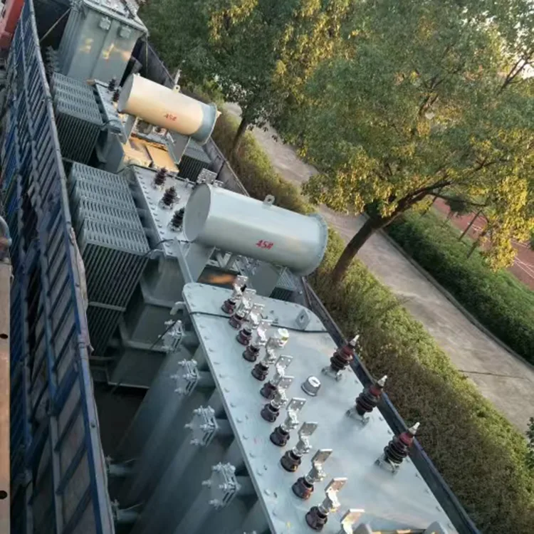
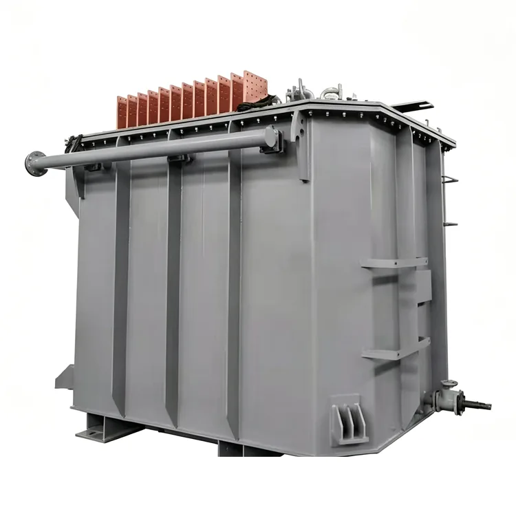
Total valve-side current can reach tens of thousands of amperes; even after splitting, the current in a single branch remains very high. Lead-outs typically utilize multiple parallel copper busbars; uniform spacing and transposition measures are required to ensure even current distribution across the parallel bars and prevent localized overheating. Some products feature large-area terminal boards on the tank sidewall to minimize contact resistance.
Leakage Flux and Structural Component Heating
High-current windings generate intense leakage magnetic fields, inducing eddy currents in clamping structures, tie plates, and tank walls. Multi-split designs often require magnetic shielding on the tank's inner walls, as well as slotted clamps or the use of non-magnetic materials, to reduce stray losses. Cooling Method Selection
Large-capacity multi-split rectifier transformers typically employ forced-oil water-cooling (OFWF) or forced-oil air-cooling (OFAF). Cooler selection must account for the additional heat generated by harmonic-induced losses; thermal calculations cannot rely solely on estimates based on power-frequency sinusoidal currents.
Manufacturing and Testing
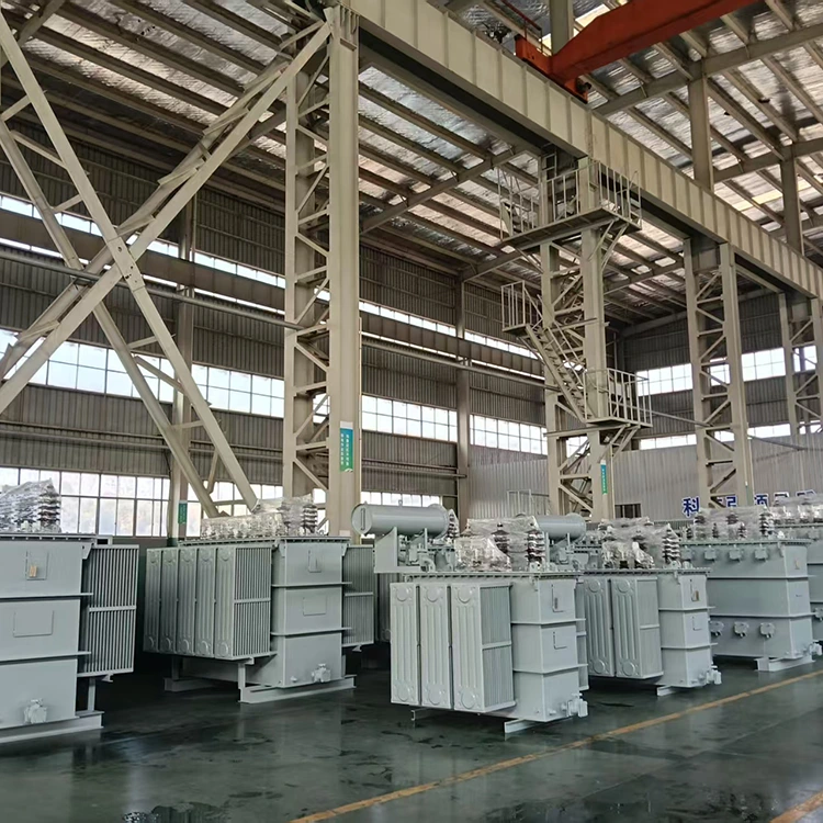
Windings are wound using transposed conductors or multiple parallel conductors, with reliable insulating barriers placed between split branches. After assembly, the active part undergoes processing in a kerosene vapor phase vacuum drying system to thoroughly remove moisture and gases from the insulation components.
In addition to standard factory tests, measurements are conducted for split impedance between branches, inter-branch insulation resistance, and withstand voltage levels. For products rated 35 kV and above, lightning impulse tests and partial discharge measurements are performed. Specific requirements include temperature rise tests for each split branch to verify the hot-spot temperature rise under rated harmonic currents.
Test data is archived by serial number, ensuring traceability back to the winding, core stacking, and drying processes. The company holds ISO 9001:2015, ISO 14001, and ISO 45001 certifications.
FAQ
Q: What is the relationship between "multi-split" and "multiplexing"?
"Multi-split" refers to a structural design where the valve-side winding is divided into multiple branches capable of independent power supply. "Multiplexing" refers to the use of phase shifting to create phase differences between rectifier bridges, thereby eliminating grid-side harmonics. The two concepts can be combined; for example, a dual-split transformer might supply power to two 6-pulse bridges separately, with phase shifting applied to form a 12-pulse system.
Q: How is split impedance typically determined?
Split impedance values are specified by the rectifier manufacturer or system designer, based primarily on short-circuit current limitations, circulating current control between parallel bridges, and DC voltage regulation requirements. The transformer manufacturer adjusts the winding arrangement and cooling duct dimensions to meet the target impedance, subsequently verifying the design through testing.
Q: What are the benefits of in-phase inverse-parallel connection?
By connecting adjacent split windings in an anti-parallel configuration, the current directions are made opposite, causing the resulting leakage magnetic fields to cancel each other out; this significantly reduces slot leakage flux, heating in structural components, and electromagnetic forces on the windings. This design is widely used in low-voltage, high-current rectifier transformers for electrolytic applications.
Q: Can the individual branches of a multi-split transformer operate independently?
Yes. The valve-side branches are electrically independent, allowing the corresponding rectifier bridges to be switched on or off separately. When some branches are taken out of service, the grid-side winding and the core remain operational; however, care must be taken to ensure the load on the remaining branches does not exceed design limits.
Q: How should the forced oil-circulation water-cooling system be maintained?
The water-cooling system requires regular inspection for leaks in the cooling water piping and monitoring of the differential pressure between the water and oil circuits to prevent water ingress into the oil. Internal scaling in the coolers can impair heat dissipation; cleaning schedules should be determined based on water quality. Before the transformer is energized, the cooling system must be started first; upon shutdown, the cooling system should be the last to stop.
Application Scenarios
Multi-split rectifier transformers are primarily used in industrial settings requiring high-current DC power, such as:
● Large-scale electrolytic workshops for aluminum, copper, and zinc
● Chlor-alkali ion-exchange membrane electrolytic cells
● Graphitization furnaces and DC electric arc furnaces
● Large-scale automated electroplating production lines
● DC power supply systems for non-ferrous metal smelting
These applications demand high reliability, uniform current distribution, and ease of maintenance — areas where the multi-split structure offers significant advantages.
Related Category
Send Inquiry
Contact Info
-
Address
No. 20, Bai'e Road, Hecun Town, Jiangshan City, Zhejiang Province,CHINA
-
Tel
-
Email
Send specs for power, furnace or rectifier transformers and get a customized quotation and price list, direct from Yulan Transformer factory. Bulk orders welcome.
News Recommendations




