
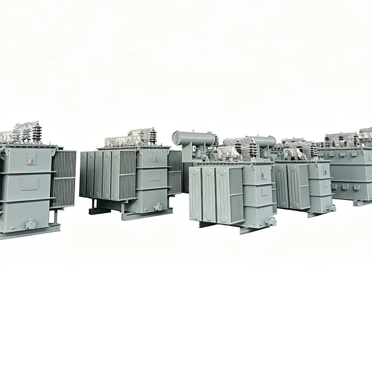
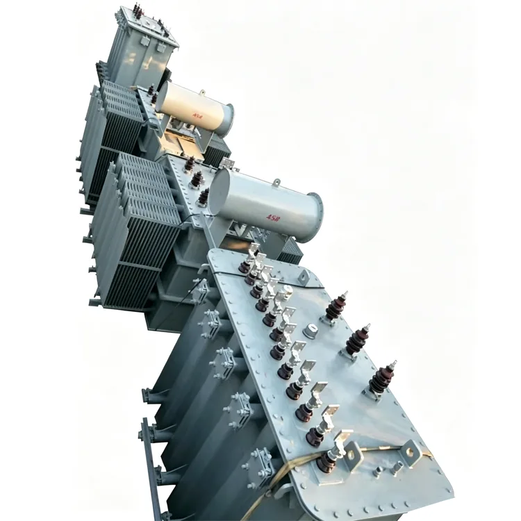
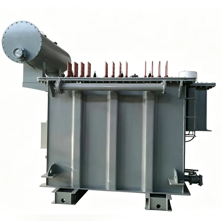
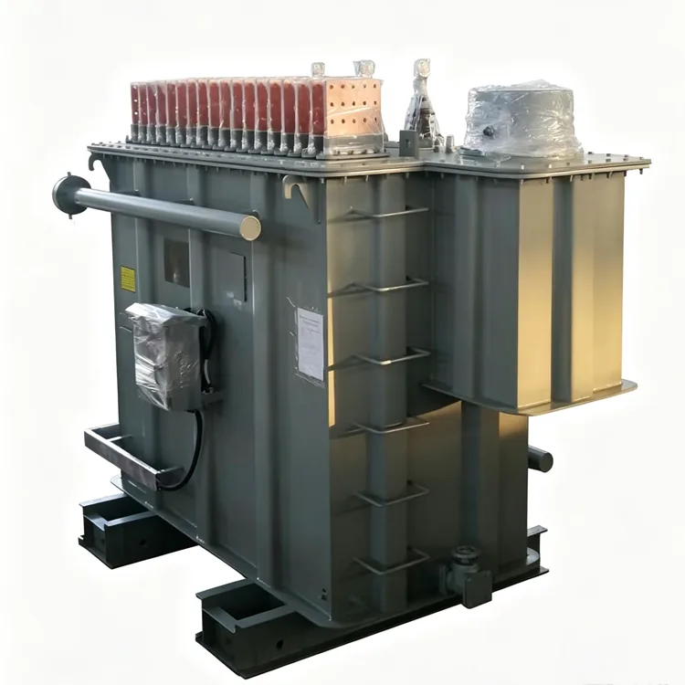
Multi-winding Rectifier Transformer
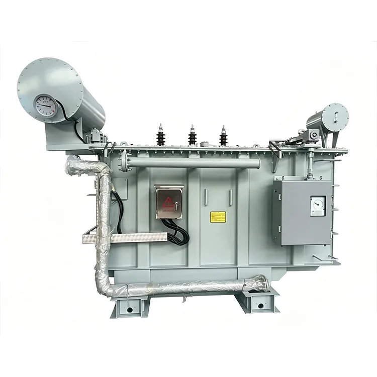
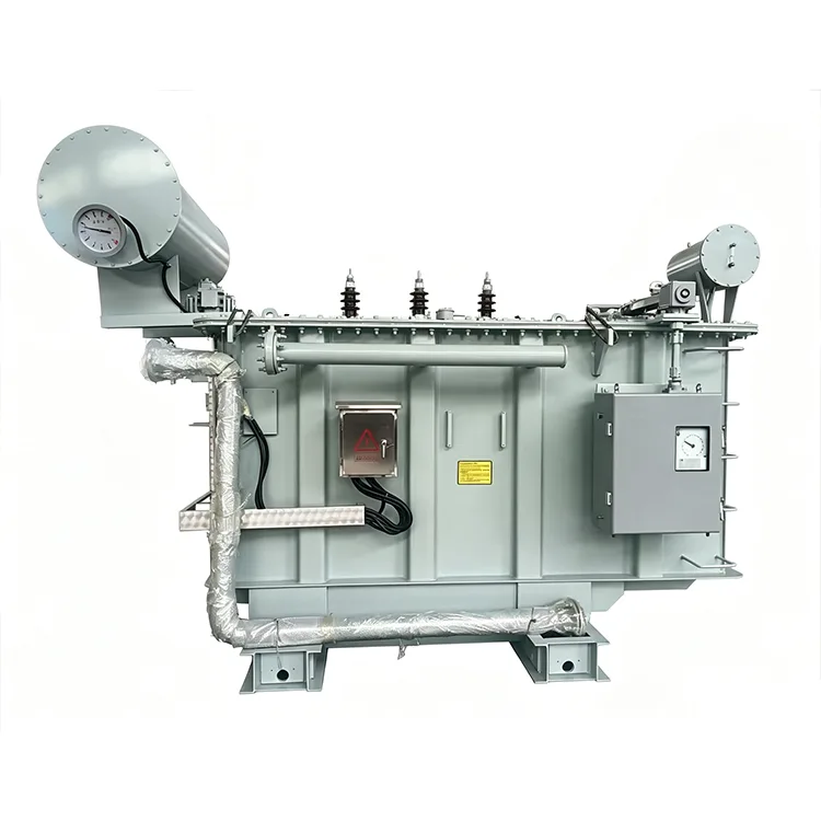
Yulan manufactures multi-winding rectifier transformers with capacities ranging from 630 kVA to 80,000 kVA, widely used in high-current electrolysis, electroplating, industrial electric furnaces, and DC power supply systems. You can request a quote, specify split-winding configurations, or order transformers tailored to the voltage and impedance requirements of your specific project.
When the valve-side current of a rectifier installation reaches tens of thousands of amperes, a conventional single winding becomes difficult to manufacture and terminate safely. Conductor cross-sections grow beyond practical limits, and local hot spots become harder to control. Splitting the valve-side winding into several independent branches is one way to manage this. Each branch feeds its own rectifier bridge, so the current per branch stays within design limits. Yulan Transformer produces multi-winding rectifier transformers from 630 kVA up to 80,000 kVA, with primary voltage options of 6 kV, 10 kV, 15 kV, 22 kV, and 35 kV.
Function of the Split Structure
Once the valve-side winding is split, the current in each branch is smaller. Conductors and busbars become easier to size and route. The branches remain coupled through the core, and a split impedance appears between them. This impedance limits how much a fault in one branch disturbs the others. It also helps suppress circulating currents between parallel rectifier bridges.
In electrolysis duty, split windings are often used with same-phase inverse parallel connections. Two branches share the same voltage phase but their leads are arranged in opposite directions. The resulting magnetic fields partially cancel, which reduces leakage flux in the winding ducts and cuts stray losses in structural steel.
Typical Split Arrangements
Double split
Two independent valve-side branches feed two rectifier bridges. This is the most common arrangement in medium-capacity electrolysis or electroplating supplies.
Triple and quadruple split
Three or four branches are used when the total DC current is very high or when the process needs several independently controllable DC outputs. Each branch can be taken out of service without affecting the others.
Axial and radial split
Axial splitting places winding sections along the height of the core limb. Radial splitting arranges windings in layers through the core window. The two methods influence impedance and leakage flux differently, so the choice depends on the rectifier parameters and the required short-circuit behavior.
Rating and Connection Data
|
Item |
Parameter |
|
Applicable standards |
IEC, GB, ANSI/IEEE, NEMA, and project-specific specifications |
|
Rated capacity |
630 kVA to 80,000 kVA |
|
Primary rated voltage |
6 kV, 10 kV, 15 kV, 22 kV, or 35 kV |
|
Secondary voltage |
Set by the rectifier circuit, generally 100 V to 1500 V |
|
Rated frequency |
50 Hz or 60 Hz |
|
Phase |
Three-phase |
|
Split type |
Double, triple, quadruple, or as specified |
|
Valve-side connection |
Same-phase inverse parallel, wye, delta, or zigzag |
|
Split impedance |
10% to 25% typical, based on rectifier requirements |
|
Short-circuit impedance |
6% to 15% or as specified |
|
Cooling method |
OFWF, ONAF, or ONAN |
|
Voltage regulation |
Off-circuit or on-load tap changing |
Engineering Details
Split impedance is one of the more important parameters in these transformers. It affects current sharing between bridges and the peak current during a valve-side fault. A low split impedance means a fault in one branch produces a large disturbance in the others. A high value adds losses and worsens the DC output regulation. The impedance target is normally supplied by the rectifier designer, and the transformer manufacturer achieves it by adjusting winding positions and cooling duct dimensions.
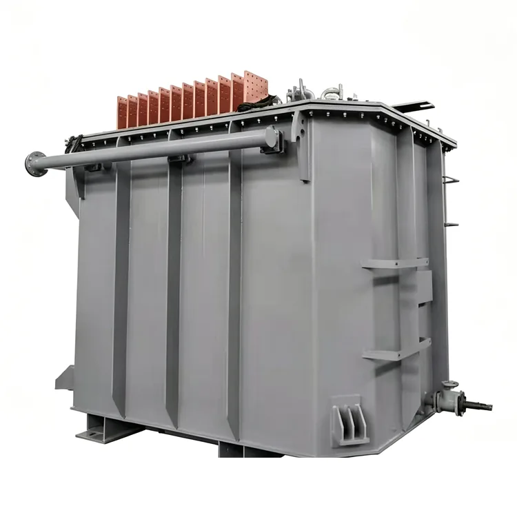
Valve-side leads remain a challenge even after splitting. Parallel copper bars are common, with careful spacing and transposition to keep current distribution even. Some designs use large terminal boards on the tank wall to reduce contact resistance and make field connections easier.
Strong leakage fields from high-current windings also cause eddy current heating in the tank and clamping structures. Magnetic shielding is usually added to the inner tank walls for larger units. Clamping plates may be slotted or made from non-magnetic material to cut stray losses.
Cooling selection should not be based only on sinusoidal current. Harmonic currents from the rectifier add extra losses, so the cooler rating must include this margin. Forced oil water cooling is common in very large electrolysis transformers, while forced air cooling is often sufficient for medium ratings.
Production and Verification
Windings use transposed conductors or multiple parallel conductors. Insulation barriers are placed between split branches. After assembly, the core and coil unit goes through a kerosene vapor phase vacuum drying process to remove moisture and gas.
Routine tests include winding resistance, voltage ratio, insulation resistance, power frequency withstand, induced overvoltage, no-load loss, load loss, and short-circuit impedance. In addition, the split impedance between branches is measured, and insulation between branches is verified. Lightning impulse and partial discharge tests are performed for primary voltages of 35 kV and above. Temperature rise tests with a specified harmonic spectrum can be arranged when the purchaser supplies the expected load profile.
Test results are stored by serial number and can be traced back to winding, core stacking, and drying records. The company holds ISO 9001:2015, ISO 14001, and ISO 45001 certifications.
Questions Before Ordering
What is the relationship between multi-winding and multi-pulse?
They are separate concepts. Multi-winding means the valve-side winding is divided into branches that can supply different bridges. Multi-pulse means those bridges are phase shifted to cancel primary-side harmonics. A double-split transformer can feed two bridges that are phase shifted by 30° to create a 12-pulse system.
Who determines the split impedance?
The rectifier manufacturer or the electrical system designer provides the target value. The transformer manufacturer then designs the winding layout to meet it and confirms the result during testing.
What makes same-phase inverse parallel connection useful?
It reduces the net leakage field inside the transformer. Since the two branch currents flow in opposite directions, their fields partially cancel. This lowers structural heating and reduces electromagnetic forces on the windings.
Can individual branches be run while others are shut down?
Yes. Each valve-side branch is independent, so the corresponding rectifier bridge can be switched separately. The primary winding and core remain energized, but the active branches must stay within their design current limits.
How is a forced oil water cooling system maintained?
Oil pressure must always exceed water pressure so any leak flows from oil to water, not the reverse. Water piping should be inspected for scale and leaks on a regular schedule. The cooling system must start before the transformer is energized and continue running after it is shut down.
Where These Transformers Are Used
Typical installations include large aluminum, copper, and zinc electrolysis halls, chlor-alkali membrane electrolysis plants, graphitization furnaces, DC arc furnaces, and automated electroplating lines. These processes require stable DC current at very high levels, and the multi-winding construction helps maintain even current sharing and manageable lead sizes.
Production Capability
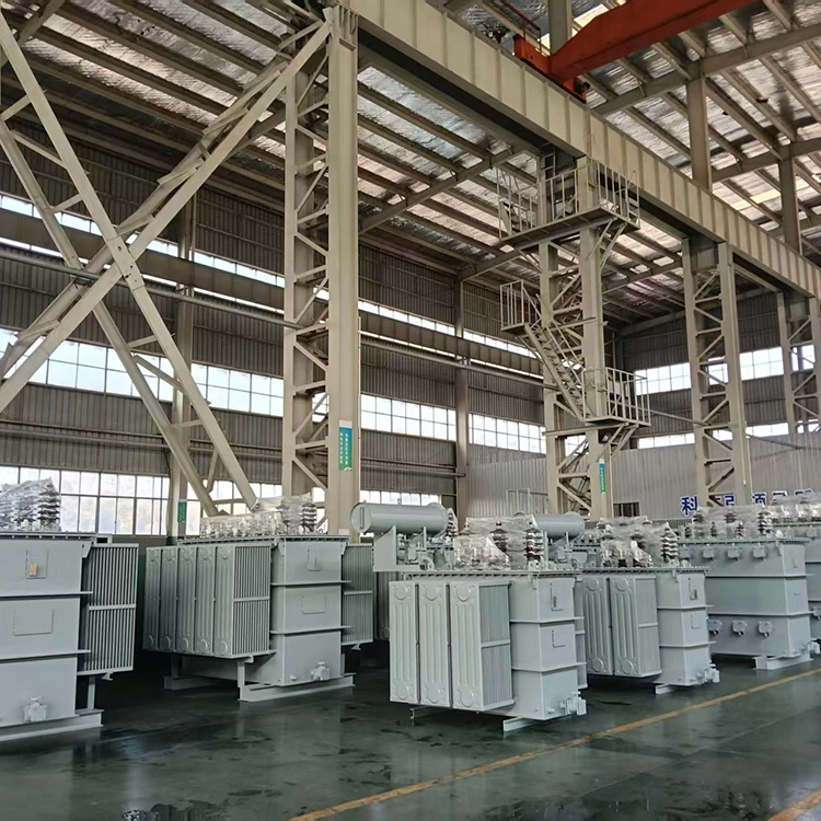
Yulan Transformer has built furnace and rectifier transformers since 1999. The factory operates under 110 kV class conditions, with an 80-ton lifting capacity, a 400 kW kerosene vapor phase vacuum drying system, a 1,200 kV impulse test system, and a 400 kV partial discharge free power frequency test transformer. These facilities support the insulation processing and factory testing of large multi-winding rectifier transformers.
For split impedance calculations, project-specific winding arrangements, or outline drawings, contact the Yulan Transformer technical department.
Related Category
Send Inquiry
Contact Info
-
Address
No. 20, Bai'e Road, Hecun Town, Jiangshan City, Zhejiang Province,CHINA
-
Tel
-
Email
Send specs for power, furnace or rectifier transformers and get a customized quotation and price list, direct from Yulan Transformer factory. Bulk orders welcome.
News Recommendations




