
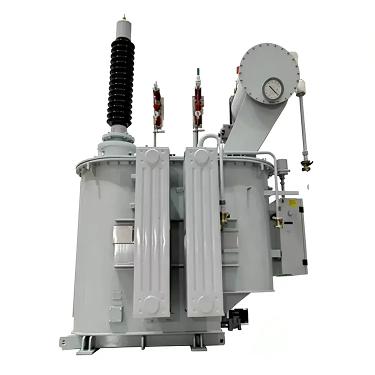
Oil-Immersed On-Load Tap-Changing Arc Suppression Coil
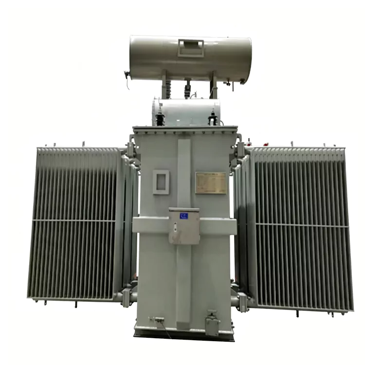
Manufactured by Jiangshan Yulan Transformer Co., Ltd., the Oil-Immersed On-Load Tap-Changing Arc Suppression Coil (Petersen coil) serves 6–66 kV distribution networks. It enables adjustable neutral-point compensation by on-load tap changing and automatic control to reduce capacitive earth-fault current. Inquire, order, or request a quote.
In a medium-voltage distribution network, the total capacitive earth-fault current changes as feeders, cables, and network configurations change. An Oil-Immersed On-Load Tap-Changing Arc Suppression Coil provides an adjustable inductive current through the neutral point to compensate for this capacitive component during a single-phase earth fault.
Also known as a Petersen coil or automatic arc suppression coil, this equipment is installed between the transformer neutral point and earth. Its inductance is adjusted through an on-load tap changer, allowing the compensation current to be changed without taking the coil out of service for each adjustment.
The oil-immersed construction provides electrical insulation and heat dissipation for the active part. The automatic control system monitors relevant network conditions and determines the required tap position within the available adjustment range.
The equipment is intended for 6–66 kV distribution systems and can be configured for substations, industrial networks, cable-heavy distribution systems, and other applications where neutral-point compensation is required.
Why the Compensation Setting Needs to Change
The capacitive current of a distribution network is not necessarily constant.
It can vary when:
· New feeders are connected
· Underground cable length increases
· Feeders are disconnected
· Network topology changes
· Operating sections are transferred
· The proportion of cable and overhead line changes
A fixed arc suppression coil has one predetermined inductance. When the network's capacitive current changes significantly, its compensation point may no longer correspond to the required operating condition.
An on-load tap-changing design addresses this issue by providing several winding tap positions. The controller can select a different position as the network condition changes.
This makes the product particularly relevant to distribution systems where the connected network is not electrically constant throughout its operating cycle.
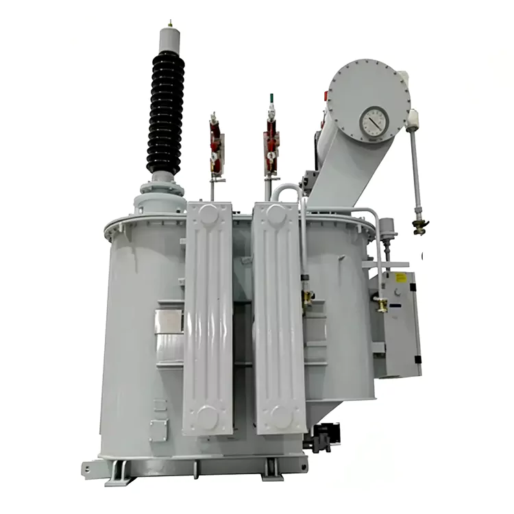
How the On-Load Compensation System Operates
Under normal conditions, the arc suppression coil is connected to the neutral point and remains ready for compensation.
When the control system identifies the relevant network condition, it determines the required inductive compensation and selects an appropriate tap position.
The electrical process can be simplified as follows:
Network capacitance → capacitive earth-fault current → compensation calculation → tap-position adjustment → inductive compensation → reduced residual fault current
During a single-phase earth fault, the inductive current from the coil offsets the capacitive component of the network fault current. When the compensation is appropriately selected, the residual current at the fault point can be reduced, which can assist arc extinction and limit the effects associated with transient earth faults.
The actual operating point should be established from the network's measured or calculated capacitive earth-fault current and the protection philosophy. The coil should therefore be treated as part of the complete neutral-point grounding system rather than as an independently selected reactor.
Internal Configuration
Magnetic Core
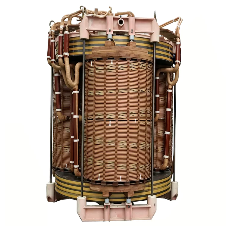
The magnetic circuit uses laminated electrical steel. Core dimensions, magnetic flux density, air-gap arrangement where applicable, and winding configuration are selected to obtain the required inductance characteristics over the specified adjustment range.
The magnetic design also considers losses, temperature rise, mechanical forces, and operating stability.
Main and Tap Windings
Copper conductors are used for the main and regulating windings. Multiple winding taps provide different effective numbers of turns.
Changing the active tap changes the coil's inductance and therefore its available compensation current.
The number of tap positions is not universal. 9, 15, and 19 positions can be configured according to the required adjustment range and electrical design.
On-Load Tap Changer
The on-load tap changer is the component that differentiates this configuration from a manually adjusted or fixed arc suppression coil.
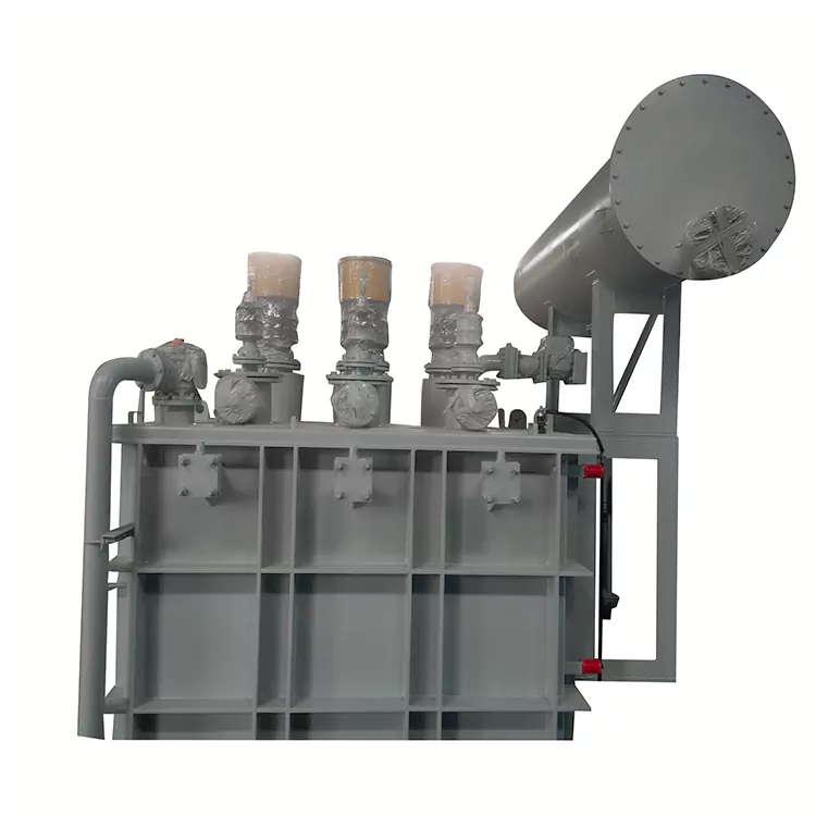
It permits the winding connection to be changed under the specified energized operating conditions. The tap changer, motor drive, control circuit, switching duty, and protection functions are selected according to the final electrical specification.
Oil-Filled Tank
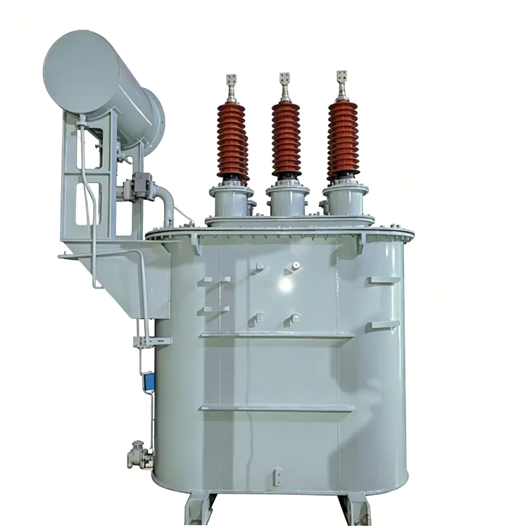
The active part is housed in an oil-filled steel tank. Transformer oil provides both insulation and heat transfer between the active components and the tank.
Depending on the selected arrangement, the oil system may include a conservator, bushings, pressure relief device, oil-level indicator, temperature monitoring devices, and associated protection components.
The exact tank and oil-preservation arrangement should follow the actual equipment configuration rather than being treated as a fixed feature for every rating.
Control and Monitoring Unit
The automatic controller forms the interface between network measurements and the tap-changing mechanism.
Depending on the project configuration, the control system can include:
· Capacitive current measurement
· Automatic compensation control
· Tap-position indication
· Local parameter display
· Manual/automatic operation
· Alarm and protection functions
· Remote communication
· Operating data transmission
· Control-system status monitoring
Communication interfaces can be selected according to the customer's substation automation system.
Technical Data
|
Parameter |
Specification |
|
Product Name |
Oil-Immersed On-Load Tap-Changing Arc Suppression Coil |
|
Other Name |
Petersen Coil / Automatic Arc Suppression Coil |
|
Product Type |
Neutral-point compensation reactor |
|
Phase |
Single-phase |
|
Connection |
Neutral point to earth |
|
Applicable System Voltage |
6–66 kV |
|
Adjustment Method |
On-load tap changing |
|
Typical Tap Positions |
9 / 15 / 19 |
|
Adjustable Quantity |
Effective winding turns / inductance |
|
Compensation Current |
Determined from network capacitive earth-fault current |
|
Insulation System |
Oil-immersed |
|
Winding Conductor |
Copper |
|
Magnetic Core |
Laminated electrical steel |
|
Rated Frequency |
According to grid requirements |
|
Cooling |
According to thermal design |
|
Oil Tank |
Oil-filled steel tank |
|
Conservator |
According to equipment configuration |
|
Temperature Monitoring |
Available according to configuration |
|
Pressure Protection |
According to tank and rating design |
|
Oil-Level Monitoring |
According to configuration |
|
Control Mode |
Automatic / manual |
|
Remote Communication |
Optional, according to project requirements |
|
Installation |
Indoor / outdoor according to environmental design |
|
Insulation Level |
According to system voltage and applicable standard |
|
Applicable Standards |
According to project specification and applicable IEC/GB standards |
Engineering note: The table describes the configurable product range. Rated compensation current, inductance range, tap positions, insulation level, short-circuit parameters, and other project-specific values should be confirmed from the network data before quotation.
What Determines the Coil Rating?
System voltage alone is not sufficient to select an arc suppression coil.
The engineering calculation normally needs to consider the following parameters.
1. System Voltage
The voltage level determines the insulation coordination, winding arrangement, bushing selection, and related dielectric requirements.
Typical systems may include 6 kV, 10 kV, 20 kV, 35 kV and higher voltage levels within the product's design range.
2. Capacitive Earth-Fault Current
This is a key input for determining the required compensation capability.
The value is affected by the total length and type of connected lines and cables as well as the network configuration.
3. Compensation Range
The required compensation range determines the inductance range and, consequently, the winding tap arrangement.
A network with a wide variation in capacitive current may require a wider adjustment range than a relatively stable network.
4. Tap Resolution
The number of available taps determines how finely the compensation setting can be changed.
The appropriate number of positions should be selected together with the required operating range and control accuracy.
5. Network Topology
The calculation should consider the normal and abnormal operating configurations of the network. If feeders are frequently transferred or switched, the controller may need to respond to larger changes in network capacitance.
6. Earth-Fault Protection
The arc suppression coil should be coordinated with the earth-fault detection and feeder-selection system.
Protection settings depend on the grounding method and residual fault current characteristics, so the grounding equipment and protection system should be designed together.
On-Load Tap-Changing and Fixed Coils
|
Aspect |
On-Load Tap-Changing Coil |
Fixed Coil |
|
Inductance |
Adjustable through taps |
Fixed |
|
Compensation Setting |
Can be changed during operation |
Predetermined |
|
Response to Network Changes |
Suitable for changing network capacitance |
Limited by fixed setting |
|
Tap Changer |
Integrated |
Not required |
|
Control System |
Usually automatic |
Simpler |
|
Engineering Complexity |
Higher |
Lower |
|
Typical Application |
Networks with variable operating conditions |
Networks with relatively stable parameters |
The main difference is not simply the presence of automation. It is the ability to modify the effective winding turns and compensation level while the equipment remains in its specified operating state.
Typical Installation Environments
This type of arc suppression coil can be considered for:
· 6–66 kV distribution substations
· Medium-voltage utility networks
· Cable-dominant distribution systems
· Mixed overhead-line and cable networks
· Industrial power distribution
· Mining and heavy-industry networks
· Substation neutral-point grounding systems
· Networks with frequently changing feeder configurations
· Distribution systems requiring adjustable earth-fault compensation
For outdoor projects, the equipment configuration should account for ambient temperature, altitude, pollution level, insulation coordination, enclosure requirements, and site conditions.
Manufacturing and Factory Capability
Jiangshan Yulan Transformer Co., Ltd. has been engaged in transformer manufacturing since 1999.
Its production scope includes power transformers, furnace transformers, rectifier transformers, reactors, and other customized electrical equipment. The company has manufacturing experience covering equipment up to the 110 kV class.
Yulan operates a manufacturing site covering approximately 35,000 m², including around 15,000 m² of workshop space. The company has more than 75 employees, including engineering and technical personnel involved in product design, production, and testing.
Production and testing resources include:
· 80-ton lifting equipment
· 400 kW kerosene vapor-phase vacuum drying system
· 1200 kV impulse test equipment
· 400 kV power-frequency withstand voltage test transformer
· 300 kV induction test generator set
· Computer-controlled vertical winding equipment
· Core slitting equipment
· Core cross-cutting equipment
· Hydraulic pressing equipment
· Foil winding equipment
· Other transformer and reactor manufacturing equipment
These facilities support the manufacture and testing of customized transformer and reactor equipment.
Quality Management and Factory Testing
Yulan operates the following management systems:
· ISO 9001:2015
· ISO 14001
· ISO 45001:2018
For an arc suppression coil, the factory inspection and test scope is determined by the final product specification, applicable standards, and customer requirements.
Depending on the project, the documentation package may include:
· Routine test records
· Insulation-related test results
· Winding resistance measurements
· Tap-position and tap-changer functional checks
· Electrical performance data
· Control-system functional tests
· Protection and alarm checks
· Nameplate information
· Technical drawings
· Factory inspection documents
Where required, product testing can be arranged according to the applicable project standard and agreed technical specification.
Project Information Buyers Should Provide
For a technical quotation, the following information is useful:
|
Required Information |
Why It Matters |
|
System voltage |
Determines primary electrical and insulation design |
|
Maximum system voltage |
Used for insulation coordination |
|
Frequency |
Defines operating conditions |
|
Neutral-point arrangement |
Determines connection method |
|
Capacitive earth-fault current |
Key input for compensation calculation |
|
Required compensation range |
Determines inductance and tap range |
|
Network diagram |
Helps identify actual network configuration |
|
Feeder/cable data |
Helps calculate network capacitance |
|
Tap requirements |
Determines adjustment resolution |
|
Short-circuit data |
Used for mechanical and electrical design |
|
Installation location |
Determines environmental requirements |
|
Altitude |
May affect insulation and cooling design |
|
Ambient temperature |
Used for thermal design |
|
Indoor/outdoor installation |
Determines enclosure and protection |
|
Control requirements |
Defines controller functions |
|
Communication protocol |
Determines remote integration |
|
Protection requirements |
Coordinates grounding and fault detection |
|
Applicable standards |
Defines design and testing requirements |
A single-line diagram and capacitive earth-fault current calculation are particularly useful when requesting a quotation.
Oil-Immersed and Dry-Type Construction
|
Item |
Oil-Immersed Arc Suppression Coil |
Dry-Type Arc Suppression Coil |
|
Insulation Medium |
Transformer oil |
Solid/cast insulation and air |
|
Heat Transfer |
Through insulating oil |
Through dry-type thermal design |
|
Oil Maintenance |
Required according to equipment arrangement |
Not applicable |
|
Larger-Rating Applications |
Available according to design |
Subject to dry-type thermal limitations |
|
Outdoor Use |
Available with suitable configuration |
Available with suitable enclosure |
|
Tap-Changer Arrangement |
Can use oil-immersed on-load tap changer |
Depends on product design |
|
Fire-Safety Considerations |
Requires consideration of oil installation |
No insulating oil |
|
Selection Factors |
Rating, environment, maintenance, insulation |
Rating, environment, thermal and insulation design |
Neither construction should be selected solely on the basis of being oil-filled or dry-type. The electrical rating, installation conditions, maintenance requirements, fire-safety requirements, and project standards should all be considered.
Frequently Asked Questions
What is an oil-immersed Petersen coil?
An oil-immersed Petersen coil is an inductive grounding device connected between a distribution network's neutral point and earth. It compensates for the capacitive component of single-phase earth-fault current.
Why use an on-load tap changer?
The capacitive earth-fault current of a distribution network can change as feeders and cables are connected, disconnected, or reconfigured. An on-load tap changer allows the coil's inductance and compensation current to be adjusted without shutting down the equipment for each change.
Is the compensation current continuously adjustable?
Not necessarily. A tap-changing coil normally provides a series of discrete operating positions. The actual adjustment resolution depends on the winding and tap-changer configuration.
Are 9, 15, and 19 taps standard configurations?
They can be used as typical configurations, but the final number of positions depends on the required compensation range, voltage rating, winding design, and selected tap changer.
How do I determine the required coil capacity?
The key input is the network's capacitive earth-fault current. Feeder length, underground cable length, network topology, voltage level, and operating configurations should be considered in the calculation.
Can the coil compensate a fault current completely?
The purpose of the coil is to compensate the capacitive component and reduce the residual earth-fault current. It should not be described as eliminating every fault current or guaranteeing arc extinction under all conditions.
Does this product replace an earth-fault protection system?
No. The arc suppression coil and the protection system perform different functions. The grounding compensation arrangement should be coordinated with earth-fault detection and feeder protection.
Can it be used in a 10 kV distribution network?
Yes. A 10 kV system can be within the product's design range. The required compensation current, inductance range, tap configuration, insulation level, and control functions still need to be calculated from the network parameters.
Can it be designed for 35 kV or 66 kV systems?
Yes, subject to the specific electrical and insulation design. Higher voltage applications require appropriate insulation coordination, bushings, clearances, testing, and protection arrangements.
What information should I send when requesting a quotation?
Provide the system voltage, frequency, capacitive earth-fault current, neutral-point arrangement, network diagram, required compensation range, installation conditions, tap requirements, control functions, and applicable standards.
About Yulan Transformer
Founded in 1999, Jiangshan Yulan Transformer Co., Ltd. manufactures transformers and reactors for utility, industrial, and other electrical applications.
The company's product range includes power transformers, furnace transformers, rectifier transformers, shunt reactors, series reactors, and customized reactor equipment.
With transformer and reactor manufacturing capability up to the 110 kV class, Yulan supports projects requiring customized electrical ratings, winding arrangements, insulation systems, tap-changing configurations, control functions, and factory testing.
For an oil-immersed on-load tap-changing arc suppression coil, the technical proposal can be developed from the customer's network parameters rather than from a standard product model alone.
Related Category
Send Inquiry
Contact Info
-
Address
No. 20, Bai'e Road, Hecun Town, Jiangshan City, Zhejiang Province,CHINA
-
Tel
-
Email
Send specs for power, furnace or rectifier transformers and get a customized quotation and price list, direct from Yulan Transformer factory. Bulk orders welcome.
Related Products
News Recommendations




