
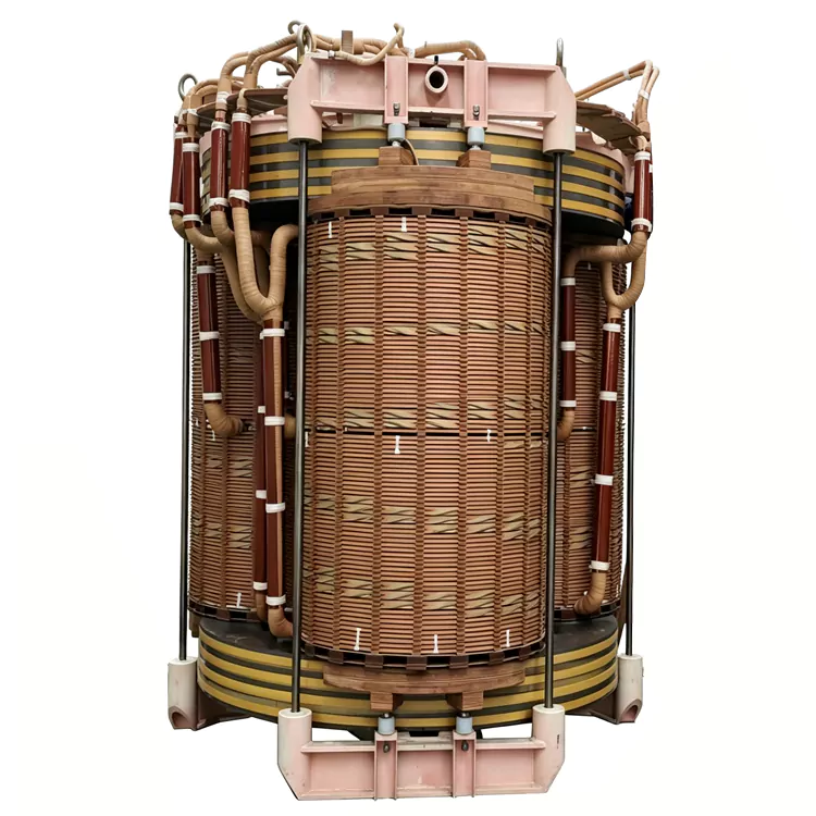
Oil-Immersed Shunt Reactor
Jiangshan Yulan Transformer Co., Ltd. manufactures oil-immersed shunt reactors for high-voltage transmission and distribution systems. The company has produced transformers and reactors since 1999. The BKS/BKD series is a fixed-capacity reactive power absorption device connected in parallel with a bus or transmission line. It absorbs capacitive charging reactive power, limits light-load and no-load overvoltage, and supports voltage distribution along long transmission lines. Single-phase and three-phase designs are available for project-specific requirements.
An Oil-Immersed Shunt Reactor is connected in parallel with a transmission line or busbar to absorb part of the capacitive reactive power generated by long overhead lines and high-voltage cable systems.
It is mainly used when line capacitance becomes significant under light-load or no-load conditions. By providing a fixed inductive reactance, the reactor helps control voltage rise and manage reactive power flow within the transmission system.
The reactor can be supplied as a single-phase or three-phase unit, with the electrical rating, insulation level, cooling arrangement, and mechanical construction designed for the project.
Typical applications include 220 kV and 500 kV transmission systems, large renewable-energy transmission projects, substations, and long-distance power transmission networks.
Why Shunt Reactors Are Used on Long Lines
The capacitance of a long transmission line produces charging current even when the transmitted load is relatively low. As line length and voltage level increase, the effect of charging reactive power becomes more significant.
During light-load or no-load operation, excessive capacitive reactive power can contribute to voltage rise along the line.
A shunt reactor provides an inductive current in parallel with the system. This offsets part of the capacitive reactive power and helps keep the system voltage within the required operating range.
The basic function can therefore be expressed as:
Line capacitance → charging reactive power → voltage rise → shunt reactor absorption → improved reactive power balance
The actual reactor capacity and installation point should be determined through system studies rather than by voltage level alone.
Construction Details
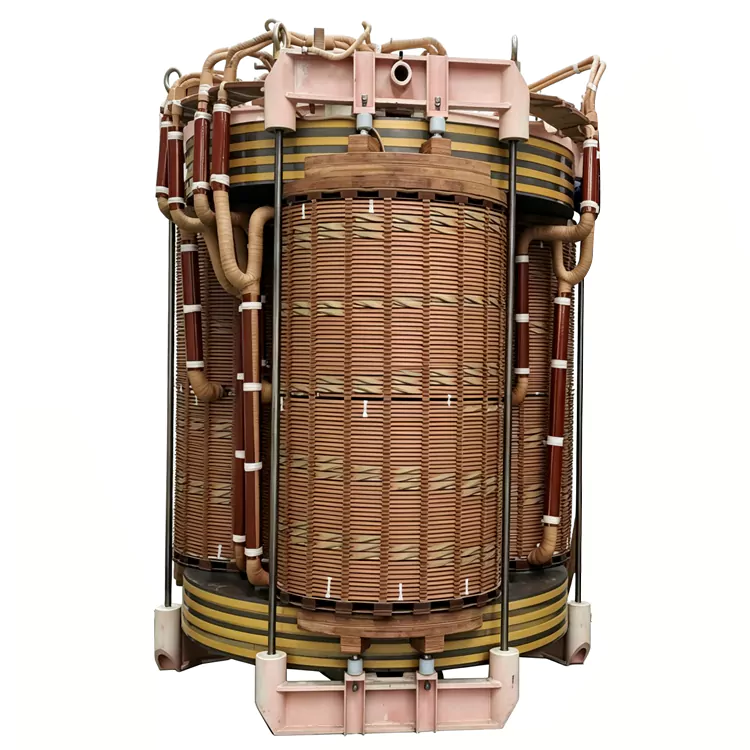
Segmented-Gap Magnetic Core
The core is assembled from electrical steel laminations with distributed air gaps. The segmented-gap arrangement is used to obtain the required inductance while controlling magnetic flux density and core saturation characteristics.
The core design also considers losses, vibration, temperature rise, and the required inductance tolerance.
High-Voltage Winding
The winding uses copper conductors with an insulation system selected according to the rated voltage and dielectric requirements.
Winding geometry, conductor cross-section, insulation arrangement, and mechanical support are determined according to the rated current, short-time conditions, and applicable test requirements.
Oil-Filled Insulation and Cooling
The active part is installed in an oil-filled steel tank. Insulating oil provides dielectric insulation and transfers heat from the core and winding to the cooling surfaces.
The cooling arrangement is selected according to the reactor rating and installation conditions.
Tank and Protection Accessories
Depending on the rating and project specification, the reactor can be equipped with:
· HV bushings
· Conservator or oil-preservation system
· Pressure relief device
· Buchholz relay
· Oil-level indicator
· Oil temperature indicator
· Temperature sensors
· Drain and oil-sampling valve
· Earthing terminals
· Lifting and transport fittings
The actual accessory configuration should follow the approved technical specification.
Technical Specifications
|
Parameter |
Specification |
|
Product Name |
Oil-Immersed Shunt Reactor |
|
Series |
BKS / BKD, according to product configuration |
|
Configuration |
Single-phase / Three-phase |
|
Installation |
Parallel connection to busbar or transmission line |
|
Main Function |
Absorption of capacitive reactive power |
|
Applicable Voltage |
According to project requirements; high-voltage and extra-high-voltage applications available |
|
Rated Capacity |
According to project requirements |
|
Rated Frequency |
According to grid requirements |
|
Rated Current |
According to system design |
|
Rated Inductance / Reactance |
According to project requirements |
|
Magnetic Core |
Laminated electrical steel with segmented air gaps |
|
Winding Conductor |
Copper |
|
Insulation |
Oil-immersed |
|
Cooling |
According to thermal design |
|
Insulation Level |
According to system voltage and applicable standard |
|
Installation Environment |
Indoor / outdoor according to design |
|
Tap Changing |
Fixed reactance; no routine tap adjustment |
|
Protection Accessories |
According to rating and specification |
|
Applicable Standards |
According to project specification and applicable IEC/GB standards |
Note: Shunt reactors are system-specific equipment. The required Mvar rating, reactance, losses, insulation level, short-circuit withstand, cooling method, and installation arrangement should be confirmed from the electrical design.
Single-Phase and Three-Phase Configurations
|
Configuration |
Typical Consideration |
|
Single-Phase |
Useful where the transmission system requires individual phase units or a bank arrangement |
|
Three-Phase |
Integrated three-phase configuration for suitable substation and transmission applications |
The final arrangement depends on system voltage, required reactive compensation, transport limitations, substation layout, protection scheme, and project standards.
Where the Reactor Is Typically Installed
Oil-immersed shunt reactors are commonly considered for:
· 220 kV and 500 kV substations
· Long-distance high-voltage transmission lines
· Large renewable-energy transmission projects
· Wind and photovoltaic power transmission systems
· Large power-generation evacuation systems
· High-voltage cable transmission systems
· Networks with significant light-load voltage rise
· Busbars requiring fixed inductive reactive compensation
For offshore or other demanding environments, the equipment enclosure, insulation coordination, corrosion protection, cooling system, and installation conditions require additional engineering review.
How to Select the Required Reactor
A shunt reactor should be selected from the network's operating study rather than simply matching the reactor to the system voltage.
Important inputs include:
System voltage and frequency
Define the basic electrical and insulation requirements.
Required reactive compensation
The required Mvar rating determines how much capacitive reactive power the reactor is intended to absorb.
Installation location
The effect of a reactor depends on whether it is connected to a busbar, line end, transformer tertiary, or another designated point.
Light-load operating condition
The expected minimum-load condition is important when evaluating voltage rise and the required compensation level.
Transmission-line parameters
Line length, conductor arrangement, cable sections, and system configuration affect charging capacitance.
Short-circuit conditions
Mechanical and thermal withstand requirements should be considered during the design.
Harmonic environment
Where significant harmonic currents are present, the reactor design should be checked for additional losses, heating, and waveform effects.
Oil-Immersed vs. Dry-Type Shunt Reactors
|
Factor |
Oil-Immersed |
Dry-Type |
|
Insulation Medium |
Transformer oil |
Solid/cast insulation and air |
|
Heat Transfer |
Oil-based cooling |
Dry-type thermal design |
|
Voltage Range |
Suitable for high-voltage applications according to design |
More commonly used for lower-voltage applications |
|
Capacity |
Available for large ratings according to design |
Limited by dry-type thermal and insulation design |
|
Outdoor Installation |
Common with suitable configuration |
Possible with suitable enclosure |
|
Oil Maintenance |
Required |
Not applicable |
|
Fire-Safety Requirements |
Oil containment and site provisions may be required |
No insulating oil |
|
Typical Selection |
High-voltage transmission and large-capacity applications |
Applications where oil-free construction is required |
The choice should be based on voltage, Mvar rating, installation environment, fire-safety requirements, maintenance arrangements, and project specifications.
Manufacturing and Testing Capability
Jiangshan Yulan Transformer Co., Ltd. was established in 1999 and manufactures transformers and reactors for utility, industrial, and energy applications.
Yulan has manufacturing capability up to the 110 kV class, with approximately 35,000 m² of site area and 15,000 m² of workshop space.
Production and testing resources include:
· 80-ton lifting equipment
· 400 kW kerosene vapor-phase vacuum drying system
· 1200 kV impulse test equipment
· 400 kV power-frequency withstand voltage test transformer
· 300 kV induction test generator set
· Computer-controlled vertical winding equipment
· Core slitting and cross-cutting equipment
· Hydraulic pressing equipment
· Foil winding equipment
Yulan operates ISO 9001:2015, ISO 14001, and ISO 45001:2018 management systems.
For a specific shunt reactor, the factory test scope and documentation are established according to the approved technical specification and applicable standards.
Technical Documents for Procurement
For a shunt reactor quotation, buyers should provide:
1. System voltage and maximum system voltage
2. Frequency
3. Required Mvar rating
4. Installation point
5. Transmission-line length and configuration
6. Light-load operating conditions
7. Required reactance or impedance, if specified
8. Rated current
9. Insulation level
10. Short-circuit parameters
11. Cooling requirements
12. Indoor or outdoor installation
13. Ambient temperature and altitude
14. Applicable IEC/GB or local standards
15. Required factory and type tests
A single-line diagram and system study data are particularly useful when determining the required reactor rating.
Frequently Asked Questions
What does a shunt reactor do?
A shunt reactor absorbs inductive reactive power from the system to offset part of the capacitive charging reactive power of transmission lines or cables. This helps manage voltage under light-load conditions.
Why are shunt reactors used on long transmission lines?
Long high-voltage lines have greater charging capacitance. Under light-load or no-load conditions, this can contribute to voltage rise. A shunt reactor provides fixed inductive compensation to counter this effect.
Is a shunt reactor the same as a series reactor?
No. A shunt reactor is connected in parallel with the system and primarily absorbs capacitive reactive power. A series reactor is connected in series with a circuit and serves different functions, such as current limiting, filtering, or capacitor-bank protection.
Is the reactor capacity adjustable?
The BKS/BKD configuration described here is a fixed-reactance shunt reactor. Its normal operating reactance is not adjusted through an on-load tap changer.
How is the required Mvar rating determined?
The required rating depends on the line's charging reactive power, operating voltage, line length, minimum-load condition, installation point, and the desired voltage-control range. A system study is normally required.
Can it be used with renewable-energy transmission projects?
Yes. Shunt reactors can be used in renewable-energy collection and transmission systems where long lines or cables produce significant capacitive charging effects. The actual requirement should be confirmed through the project's reactive-power and voltage study.
Can Yulan manufacture a customized shunt reactor?
The reactor can be designed around project-specific voltage, Mvar rating, reactance, insulation level, cooling, installation, and testing requirements. The final configuration should be confirmed from the customer's technical specification.
About Yulan Transformer
Founded in 1999, Jiangshan Yulan Transformer Co., Ltd. manufactures power transformers, furnace transformers, rectifier transformers, shunt reactors, series reactors, and other customized electrical equipment.
The company's manufacturing and testing facilities support electrical equipment up to the 110 kV class, with dedicated equipment for winding, core processing, vacuum drying, high-voltage testing, and assembly.
For an oil-immersed shunt reactor project, Yulan can review the system study data and prepare a technical configuration covering the required Mvar rating, reactance, insulation system, cooling arrangement, accessories, and factory testing.
Related Category
Send Inquiry
Contact Info
-
Address
No. 20, Bai'e Road, Hecun Town, Jiangshan City, Zhejiang Province,CHINA
-
Tel
-
Email
Send specs for power, furnace or rectifier transformers and get a customized quotation and price list, direct from Yulan Transformer factory. Bulk orders welcome.
Related Products
News Recommendations




