
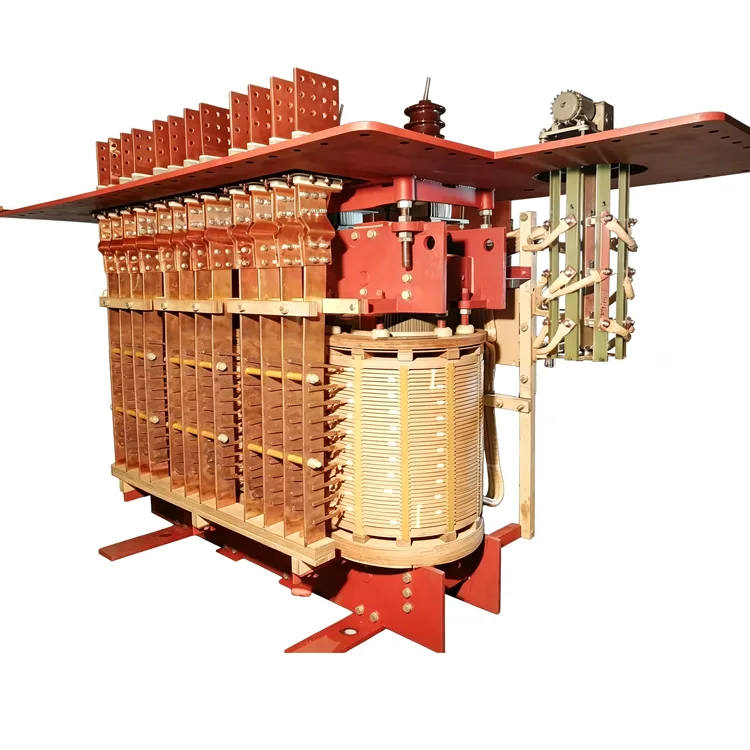
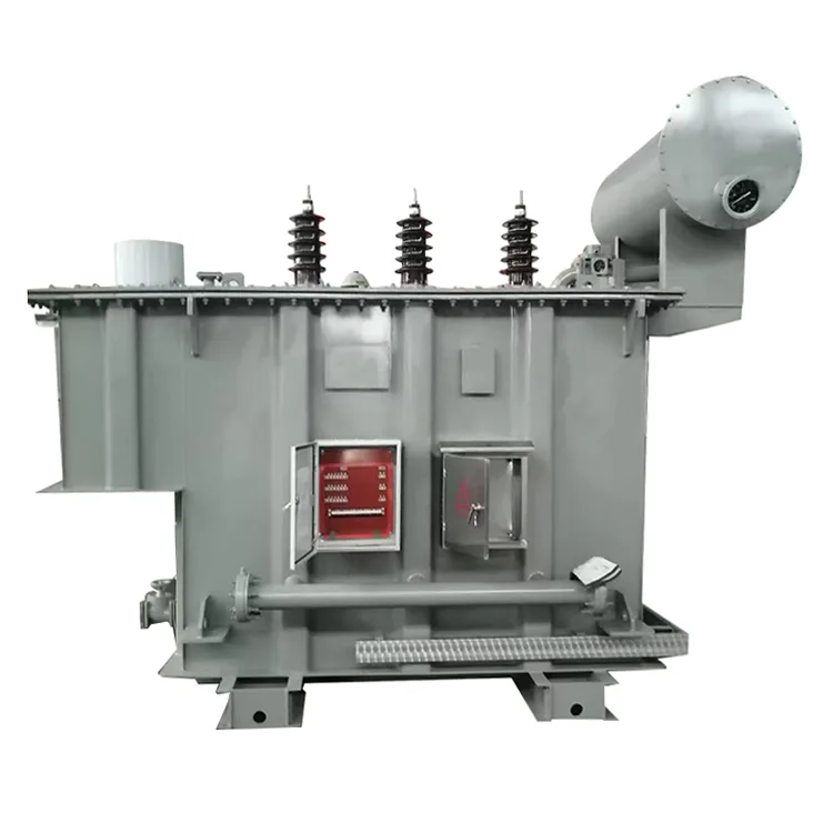
Special Transformer for Electric Arc Furnace
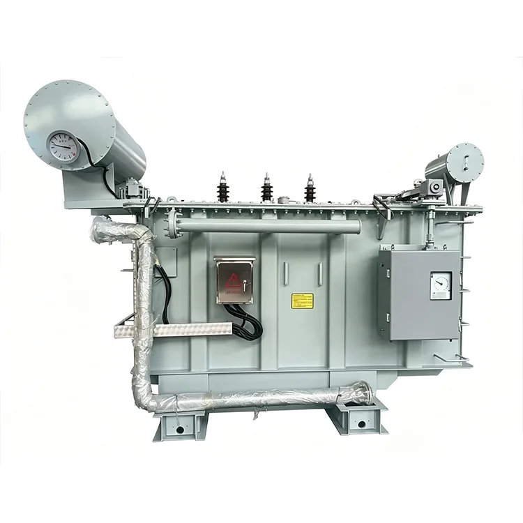
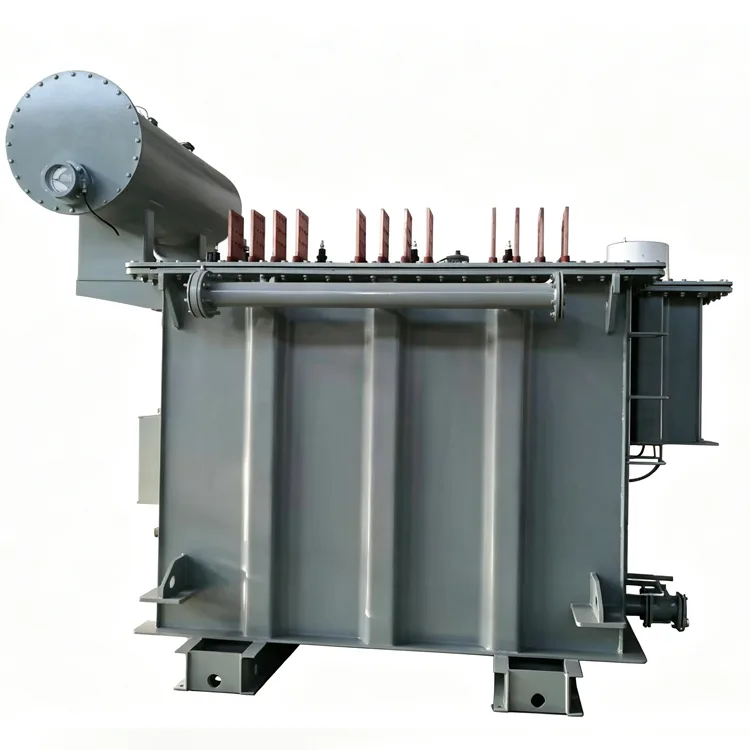
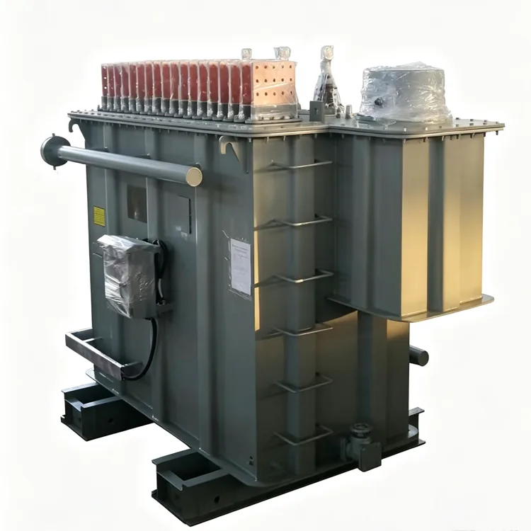
To meet the demands of rigorous electric arc furnace operating conditions, Yulan Transformer offers specialized transformers with capacities ranging from 1,000 to 80,000 kVA, supporting primary voltages of 6–110 kV and customizable secondary parameters. This Special Transformer for Electric Arc Furnace series is specifically designed and manufactured to withstand load fluctuations and frequent short-circuit conditions. Contact us today to inquire, request a quote, or order customized products.
Electric arc furnace duty places demands on a transformer that are not seen in standard distribution or power transformer service. Load current swings from open circuit to near short circuit within seconds, and the Special Transformer for Electric Arc Furnace must absorb repeated mechanical shocks while maintaining stable arc voltage. Yulan Transformer has produced furnace transformers since 1999. The arc furnace series covers 1000 kVA to 80,000 kVA, with primary voltages of 6 kV, 10 kV, 15 kV, 22 kV, 35 kV, or 110 kV. Secondary voltage and current are matched to the furnace type and melting profile. Design references include IEC 60076 series, GB/T 10229, and project-specific furnace specifications.
Load Behavior in Arc Furnace Service
During the meltdown phase, scrap movement causes frequent electrode short circuits. Secondary current can reach 2 to 3 times rated value for short intervals, and this occurs repeatedly throughout the heat. Windings and clamping structures are therefore designed for fatigue-level mechanical stress, not just steady-state temperature rise.
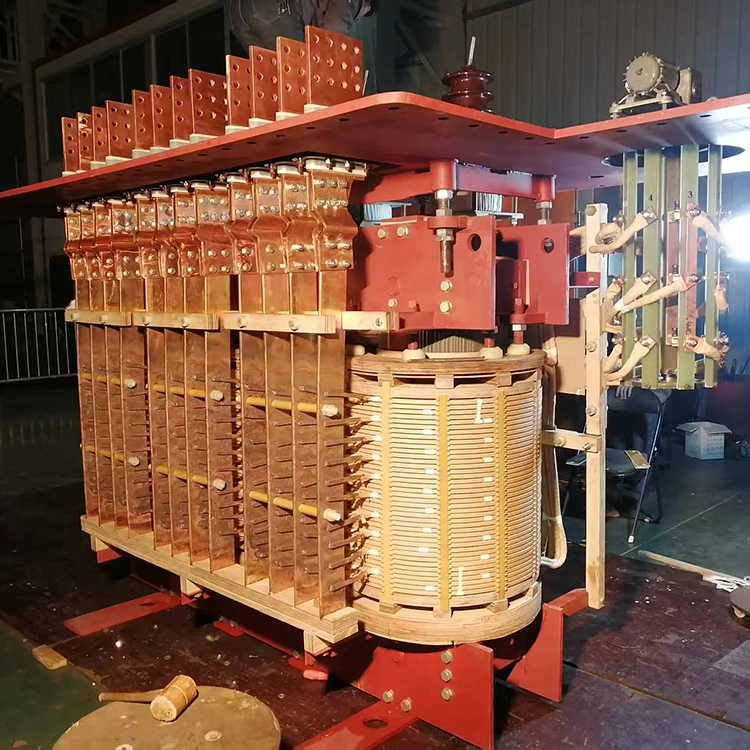
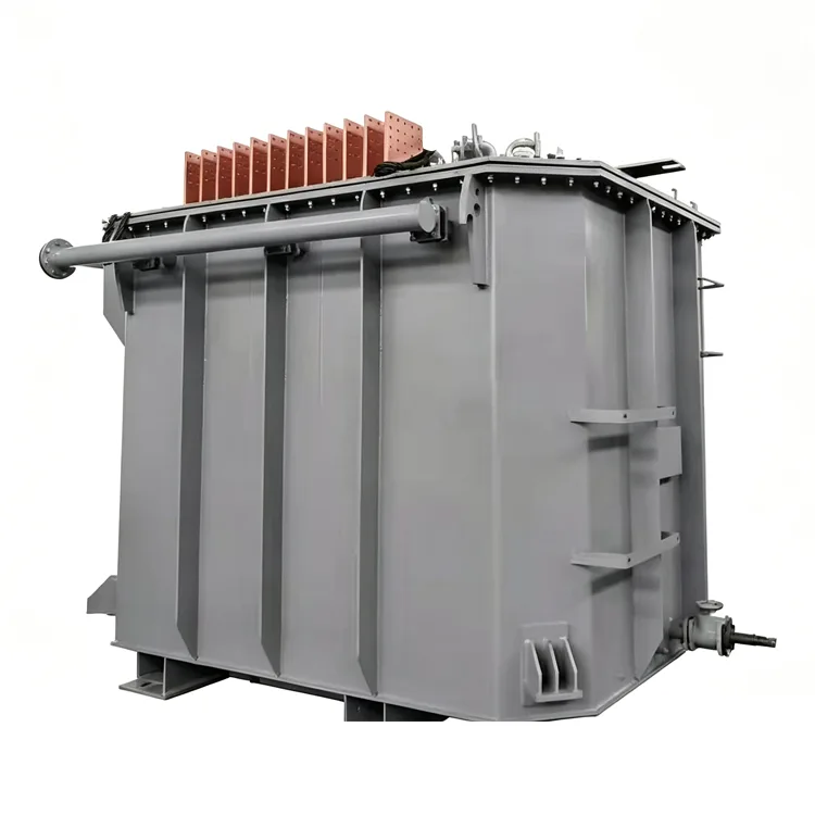
Secondary voltage is low, commonly between 100 V and 800 V, while secondary current may exceed 30,000 A on larger furnaces. This leads to multi-conductor windings, heavy copper bar leads, and large terminal boards on the tank wall. Short-circuit impedance is also higher than in ordinary transformers, typically 6% to 12%, to limit current peaks and stabilize the arc. The exact value depends on the furnace process and is normally specified by the furnace builder or electrical designer.
Configurations
Without series reactor
Used when the grid short-circuit capacity is sufficient and the furnace process is stable. The system is simpler, with smaller footprint and lower capital cost. Most small and medium furnaces use this arrangement.
With series reactor
A reactor is connected on the primary or secondary side to further limit short-circuit current and improve arc stability. This is common when the grid is weak or when the early melting period causes frequent scrap cave-ins. The reactor may be built into the transformer tank or supplied as a separate unit. Built-in designs save space, while separate reactors are easier to maintain and replace.
Representative Ratings
The following tables are extracted from production records and do not represent the complete range. Final values are confirmed in the purchase specification.
Large on-load tap changer arc furnace transformers
|
Rated power (kVA) |
Primary voltage (kV) |
Secondary voltage range (V) |
Rated secondary current (A) |
Taps |
Connection |
Impedance (%) |
Cooling |
|
10000 |
35/66/110 |
280-100 |
24056 |
19 |
Dd0, Yd11, YNd11 |
7-8 |
OFWF or OFAF |
|
16000 |
35/66/110 |
353-137 |
29326 |
19 |
Dd0, Yd11, YNd11 |
6-8.5 |
OFWF or OFAF |
|
25000 |
35/66/110 |
436-184 |
37984 |
19 |
Dd0, Yd11, YNd11 |
7.5-8.5 |
OFWF or OFAF |
|
40000 |
35/66/110 |
547-223 |
48619 |
19 |
Dd0, Yd11, YNd11 |
7-8 |
OFWF or OFAF |
|
63000 |
35/66/110 |
675-277 |
62176 |
19 |
Dd0, Yd11, YNd11 |
7-8 |
OFWF or OFAF |
|
80000 |
35/66/110 |
760-310 |
69982 |
19 |
Dd0, Yd11, YNd11 |
7-8 |
OFWF or OFAF |
The first five tap positions in these units provide constant power output, and the remaining positions provide constant current output. Constant power is used during the early melting stage, while constant current suits the refining period.
6-10 kV series without reactor, selected models
|
Model |
Rated power (kVA) |
Primary voltage (kV) |
Secondary voltage (V) |
Taps |
Impedance (%) |
Cooling |
|
HS-1000/10 |
1000 |
6/6.3/10/10.5/11 |
200-98 |
5 |
24 |
ONAN |
|
HS-1600/10 |
1600 |
6/6.3/10/10.5/11 |
210-104 |
5 |
21 |
ONAN |
|
HSSP-3150/10 |
3150 |
6/6.3/10/10.5/11 |
220-110 |
5 |
7 |
ONAN/ONAF |
|
HSSPZ-7500/10 |
7500 |
10 |
240-140 |
17 |
7.5 |
ONAF |
|
HSSPZ-12500/10 |
12500 |
10 |
320-160 |
17 |
7.5 |
OFAF |
6-10 kV series with reactor, selected models
|
Model |
Rated power (kVA) |
Primary voltage (kV) |
Secondary voltage (V) |
Taps |
Impedance (%) |
Cooling |
|
HSK-800/10 |
800 |
6/6.3/10/10.5/11 |
200-98 |
4 |
8.3 |
ONAN |
|
HSK-1250/10 |
1250 |
6/6.3/10/10.5/11 |
210-104 |
6 |
9.0 |
ONAN |
|
HSK-3150/10 |
3150 |
6/6.3/10/10.5/11 |
220-98 |
6 |
7.95 |
ONAN/ONAF |
|
HSSPK-8000/10 |
8000 |
10 |
280-133 |
6 |
8.2 |
ONAF |
|
HSSP-9000/10 |
9000 |
10 |
280-127 |
6 |
8.12 |
OFAF |
20-35 kV series, selected models
|
Model |
Rated power (kVA) |
Primary voltage (kV) |
Secondary voltage (V) |
Taps |
Impedance (%) |
Cooling |
|
HSSPK-1800/35 |
1800 |
20/33/35/37.5 |
222-128 |
6 |
7.8 |
ONAN |
|
HSSPK-6300/35 |
6300 |
35 |
260-121 |
6 |
7.5 |
ONAF |
|
HSSPZ-10000/35 |
10000 |
35 |
300-140 |
13 |
8 |
ONAF |
|
HSSPZ-16000/35 |
16000 |
35 |
360-140 |
19 |
8 |
ONAF |
|
HSSPZ-31500/35 |
32000 |
35 |
489-201 |
19 |
7 |
OFWF |
|
HSSPZ-50000/35 |
50000 |
35 |
610-250 |
19 |
7.5 |
OFWF |
|
HSSPZ-63000/35 |
63000 |
35 |
673-277 |
19 |
7 |
OFWF |
Primary voltage can be designed for 60 kV or 110 kV on request. Impedance and outline dimensions will change accordingly.
Key Design Parameters
On-load tap changing
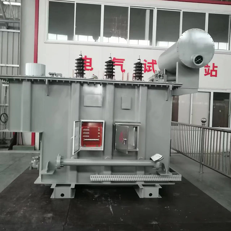
Most arc furnace transformers use an on-load tap changer to cover the different voltage needs between melting and refining. Thirteen to nineteen taps are common, and some projects require more. The tap changer adds volume to the tank and requires attention to oil flow and heat dissipation during operation.
Impedance selection
Impedance is not a fixed standard value. The furnace builder and electrical designer determine the target range based on arc stability and short-circuit current limits. The transformer manufacturer adjusts winding arrangement and leakage flux control to meet the specified value. A high impedance limits current peaks but reduces effective furnace power. A low impedance does the opposite.
Cooling
Small units use natural oil cooling or forced air cooling. Large units with high loss density use forced oil air cooling or forced oil water cooling. Water-cooled systems require the oil pressure to stay above the water pressure at all times, so any leak flows from oil to water rather than the reverse.
Secondary leads
Secondary current is extremely high, so lead cross-section, spacing, and mechanical support are specially designed. Some large units use same-phase inverse parallel connections, where adjacent lead currents flow in opposite directions. This reduces external magnetic fields and structural heating.
Manufacturing and Testing
Windings are made with transposed conductors or multiple parallel conductors to keep current distribution even. The assembled core and coil unit is dried in a kerosene vapor phase vacuum system to remove moisture and gas. Tanks and structural parts are shot-blasted and powder-coated for industrial environments.
Routine tests include winding DC resistance, voltage ratio, insulation resistance, power frequency withstand, induced overvoltage, no-load loss, load loss, and short-circuit impedance. Because of the severe operating conditions, short-circuit withstand verification is often required either as a type test or through calculation reports. On-load tap changers are operated through a full cycle before dispatch to confirm switching reliability.
The company holds ISO 9001:2015, ISO 14001, and ISO 45001 certifications. Test records are archived by serial number and can be traced to material batches and key process steps.
Selection and Operation FAQ
When is a series reactor needed?
When the grid short-circuit capacity is limited, or when early melting causes frequent scrap cave-ins, a reactor helps limit current peaks and stabilize the arc. If the grid is strong and the furnace design is mature, the reactor may be omitted. The final decision comes from the short-circuit study.
Does more tap positions mean better performance?
Not necessarily. More taps allow finer voltage adjustment across the melting and refining stages, but they also increase tap changer cost and tank size. Most furnaces work well with 13 to 19 taps, and more than 25 is uncommon.
Why is impedance higher than in a standard transformer?
Arc furnace operation involves frequent electrode short circuits. A higher impedance limits the peak short-circuit current and reduces mechanical stress on the windings. Ordinary transformers usually have 4% to 6% impedance, while arc furnace units are normally in the 6% to 12% range.
Why is secondary voltage so low?
The arc itself operates at low voltage, typically tens to a few hundred volts. The transformer secondary must match that voltage. The high power requirement then appears as very high secondary current, which is why the valve-side winding and leads are so heavily built.
What daily maintenance does a forced oil water cooling system require?
Oil pressure must remain higher than water pressure at all times. Any leak should be from oil to water, not the reverse. Cooler scaling should be checked on a schedule based on water quality. The cooling system must start before the transformer is energized and continue running after shutdown until winding temperatures drop.
Engineering Experience and Supply Scope
Yulan Transformer has built furnace transformers for ordinary arc furnaces, ladle refining furnaces, and submerged arc furnaces. Production facilities include an 80-ton lifting capacity, a 400 kW kerosene vapor phase vacuum drying system, a 1,200 kV impulse test system, and a 400 kV partial discharge free power frequency test transformer. These resources support the insulation processing and factory verification of arc furnace transformers up to 110 kV class.
Projects within the 1000 kVA to 80,000 kVA range and primary voltages from 6 kV to 110 kV can be evaluated based on the customer's single-line diagram and furnace data. For outline drawings, weight estimates, or loss calculations, contact the Yulan Transformer technical department.
Related Category
Send Inquiry
Contact Info
-
Address
No. 20, Bai'e Road, Hecun Town, Jiangshan City, Zhejiang Province,CHINA
-
Tel
-
Email
Send specs for power, furnace or rectifier transformers and get a customized quotation and price list, direct from Yulan Transformer factory. Bulk orders welcome.
News Recommendations




