
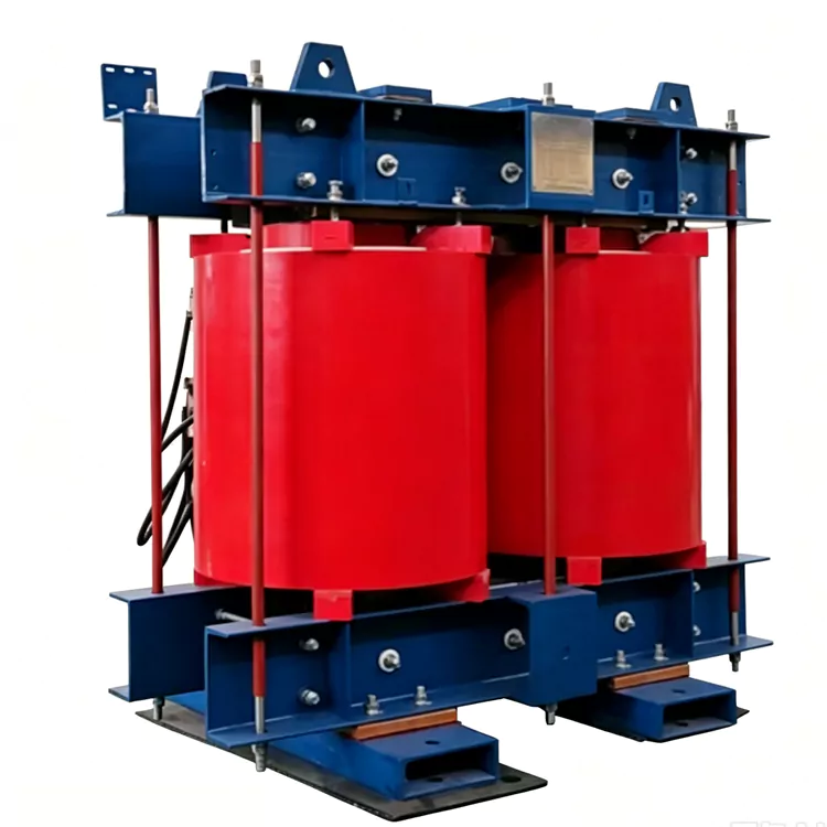
Dry-Type Arc Suppression Coil
Jiangshan Yulan Transformer Co., Ltd. manufactures dry-type arc suppression coils for 6–35 kV distribution networks. The coil is connected between the neutral point of a grounding transformer and earth. It tracks the system capacitive earth-fault current and injects an inductive current to reduce the residual fault current and extinguish the arc. The epoxy-cast design is oil-free and suitable for indoor substations, urban distribution networks, and renewable energy step-up stations where fire safety and low maintenance are required.
The dry-type arc suppression coil is a single-phase neutral grounding compensation device. It is available in three common tuning types: on-load tap-changing, DC bias, and capacitance-switching.
It works with a grounding transformer, a damping resistor, and an automatic tuning controller. The grounding transformer provides the neutral point. The coil provides adjustable inductive current. The controller measures zero-sequence voltage and system capacitance current, then adjusts the coil to the required compensation level.
The coil does not perform load reactive power compensation. Its function is earth-fault arc suppression and overvoltage control in small-current grounding systems.
System Background and Operating Principle
In 6–35 kV distribution networks, the neutral is often isolated or grounded through an arc suppression coil. Lines and cables have distributed capacitance to earth.
When a single-phase earth fault occurs, the system capacitance produces a capacitive fault current. If this current is high, the arc may persist. A persistent arc can cause arc overvoltage, insulation breakdown, and feeder tripping.
The arc suppression coil is connected to the neutral point. The controller continuously measures zero-sequence voltage and estimates the system capacitance current. It then adjusts the coil inductance. The coil outputs an inductive current that cancels the capacitive fault current. The residual current at the fault point is reduced, and the arc is extinguished.
A damping resistor is connected in series or in parallel according to the design. It limits power-frequency resonance overvoltage and improves system damping. The controller supports automatic tuning, manual operation, fault recording, faulty feeder selection, and remote communication with substation automation systems.
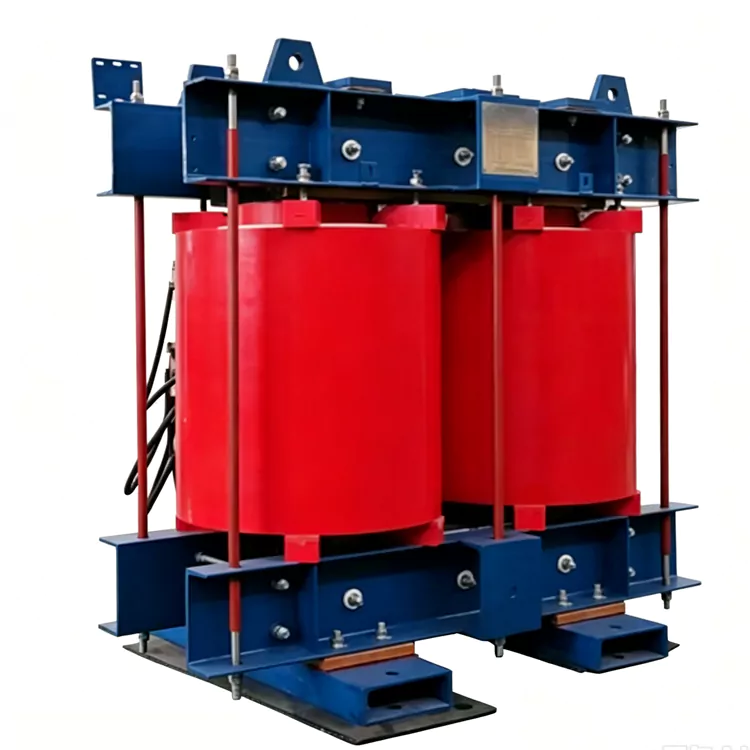
Tuning Methods
|
Tuning type |
Adjustment method |
Characteristics |
Typical use |
|
On-load tap-changing |
Motor-driven on-load tap changer; step adjustment |
Mature, reliable, no interruption during tap change |
Most 10 kV and 35 kV indoor systems |
|
DC bias |
DC excitation changes core saturation; continuous stepless adjustment |
Smooth regulation, fast response, no mechanical tap changer |
Systems requiring continuous tuning |
|
Capacitance-switching |
Switching capacitors on the secondary side to change equivalent current |
Simple structure, step adjustment |
Medium and small capacity compensation |
The final tuning type depends on system capacitance current range, required response, maintenance practice, and project preference.
Construction
|
Part |
Description |
|
Core |
High-permeability cold-rolled silicon steel, stacked core, optimized magnetic circuit, low no-load loss and low noise |
|
Epoxy-cast winding |
Copper conductor, multi-tap or regulating winding, vacuum epoxy resin casting, high insulation strength, low partial discharge |
|
Tuning component |
On-load tap changer, DC bias winding, or secondary capacitor switching unit, depending on type |
|
Damping resistor |
Limits resonance overvoltage and improves system damping |
|
Controller |
Measures zero-sequence voltage and capacitance current, calculates compensation, supports auto/manual mode, fault recording, line selection, and remote communication |
|
Temperature monitoring |
Winding temperature sensors, alarm and trip contacts |
|
Support structure |
High-strength insulating supports, vibration-damping base, compact indoor frame |
Technical Data
|
Parameter |
Range or description |
|
Rated voltage |
6 kV, 10 kV, 35 kV |
|
Type |
Single-phase, dry-type, epoxy cast |
|
Series |
XHDC |
|
Tuning method |
On-load tap-changing / DC bias / capacitance-switching |
|
Rated capacity |
Project-specific |
|
Compensation current range |
Project-specific; selected from system capacitance current |
|
Frequency |
50 Hz / 60 Hz |
|
Insulation class |
F / H |
|
Cooling |
AN / AF |
|
Partial discharge |
Low, according to standard |
|
Temperature rise |
According to GB / IEC |
|
Protection degree |
IP20, IP23, or as specified |
|
Installation |
Indoor; outdoor with enclosure |
|
Standards |
GB 1094.6, DL/T 1057, IEC 60076-6 |
Selection and Design Inputs
|
Input |
Why it matters |
|
System voltage and frequency |
Determines insulation level and basic design |
|
System capacitance current range |
Sets the compensation current range |
|
Minimum and maximum fault current |
Determines tuning range and residual current |
|
Grounding transformer neutral data |
Confirms connection and insulation coordination |
|
Tuning method preference |
On-load tap, DC bias, or capacitance-switching |
|
Damping requirement |
Determines damping resistor design |
|
Control and communication |
Defines controller functions and interfaces |
|
Installation environment |
Indoor or outdoor, altitude, humidity, pollution level |
|
Protection coordination |
Affects zero-sequence protection and line selection |
|
Project schedule |
Affects design review and production planning |
Coordination with Grounding Transformer and Damping Resistor
The grounding transformer creates the neutral point. The arc suppression coil is connected between this neutral point and earth. The grounding transformer must have low zero-sequence impedance so that the required compensation current can flow.
The damping resistor controls resonance overvoltage during tuning and fault conditions. Its value is selected with the coil reactance and system capacitance. The controller coordinates the coil, resistor, and grounding transformer.
Zero-sequence overcurrent protection, directional earth-fault protection, and faulty feeder selection must be set together with the compensation system. Incorrect coordination can cause false tripping or failure to detect the faulted feeder.
Dry-Type vs Oil-Immersed Arc Suppression Coil
|
Item |
Dry-type arc suppression coil |
Oil-immersed arc suppression coil |
|
Insulation |
Epoxy cast |
Transformer oil |
|
Fire safety |
No oil, flame-retardant |
Oil fire risk |
|
Maintenance |
Low maintenance |
Periodic oil tests |
|
Installation |
Indoor, compact |
Outdoor, oil pit required |
|
Environmental impact |
No oil leakage risk |
Oil leakage and disposal |
|
Capacity range |
Medium voltage, small and medium capacity |
Higher capacity, outdoor duty |
|
Typical use |
10 kV and 35 kV indoor substations, urban networks, renewable stations |
Large outdoor substations and special high-capacity projects |
Installation, Commissioning and Maintenance
Installation and commissioning checks typically include:
Visual inspection of the coil, controller, damping resistor, and connections
Insulation resistance measurement
Winding resistance and tap position check
Power frequency withstand voltage test
Controller parameter setting and zero-sequence signal check
Automatic tuning test with simulated capacitance current
Damping resistor and protection coordination check
Communication and remote control test
Dry-type coils require periodic visual inspection, cleaning, and temperature monitoring. The controller should be checked for correct tuning and alarm records. No oil testing is required. For outdoor installations, the enclosure and anti-condensation measures should be inspected.
Standards and Testing
The coil is designed and tested according to GB 1094.6, DL/T 1057, IEC 60076-6, and related standards. Routine tests include winding resistance, insulation resistance, power frequency withstand voltage, partial discharge, and no-load loss. Type tests and special tests are available according to project requirements.
Manufacturing and Quality Control
Jiangshan Yulan Transformer Co., Ltd. has manufactured transformers and reactors since 1999. The company operates ISO 9001:2015, ISO 14001:2015, and ISO 45001:2018 management systems. Products are tested by the National Transformer Product Testing Center of China where required.
Production and testing equipment includes vacuum casting systems, vacuum drying systems, impulse test equipment, PD-free power frequency withstand voltage test transformers, core cutting lines, winding machines, and hydraulic presses.
[ISO 9001:2015 Certificate]
[ISO 14001:2015 Certificate]
[ISO 45001:2018 Certificate]
[Factory Workshop]
[Dry-Type Casting Workshop]
[Test Bay]
[Arc Suppression Coil Assembly]
FAQ
Q: What is the difference between a dry-type arc suppression coil and a grounding transformer?
A: A grounding transformer creates a neutral point where none exists. An arc suppression coil is connected between that neutral point and earth to compensate capacitive earth-fault current. They are used together in a resonant grounding system.
Q: How does the coil extinguish the arc?
A: The controller measures the system capacitance current and adjusts the coil inductance. The coil outputs an inductive current that cancels the capacitive fault current. The residual current becomes small enough for the arc to extinguish.
Q: Which tuning method should be selected?
A: On-load tap-changing is mature and widely used. DC bias provides continuous stepless tuning. Capacitance-switching is simple and suitable for smaller systems. The choice depends on capacitance current range, response requirement, and maintenance practice.
Q: Is a damping resistor required?
A: A damping resistor is commonly used to limit resonance overvoltage and improve system damping. Its value is selected with the coil and system capacitance.
Q: Can it be used in an outdoor substation?
A: The standard design is for indoor installation. For outdoor use, an enclosure with the required protection degree and anti-condensation measures is provided.
Q: What maintenance is required?
A: Periodic visual inspection, cleaning, temperature monitoring, and controller checks. No oil testing is required for the dry-type coil.
Q: Are 50 Hz and 60 Hz designs available?
A: Yes.
Q: What information is needed for a quotation?
A: System voltage, frequency, capacitance current range, grounding transformer neutral data, tuning method preference, damping requirement, control and communication requirements, indoor or outdoor installation, altitude, pollution level, and project schedule.
Related Category
Send Inquiry
Contact Info
-
Address
No. 20, Bai'e Road, Hecun Town, Jiangshan City, Zhejiang Province,CHINA
-
Tel
-
Email
Send specs for power, furnace or rectifier transformers and get a customized quotation and price list, direct from Yulan Transformer factory. Bulk orders welcome.
Related Products
News Recommendations




