
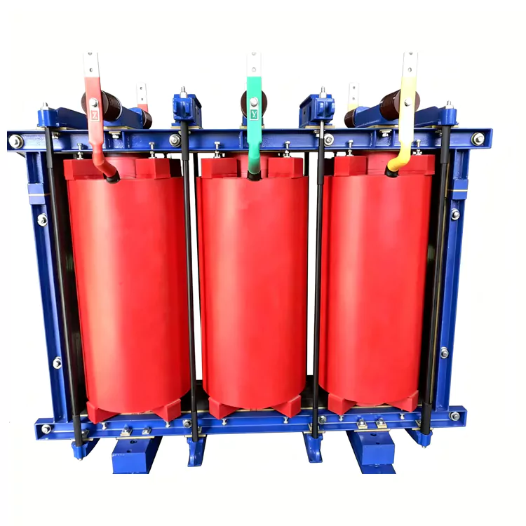
Dry-Type Filter Series Reactor
Engineered by Jiangshan Yulan Transformer Co., Ltd., the dry-type filter series reactor serves medium-voltage capacitor banks for reactive power compensation, harmonic mitigation, detuning, and inrush current limitation. It offers fixed inductance, cast-resin insulation, and oil-free construction. Custom-built options are available. Inquire, order, or request a quote.
The Dry-Type Filter Series Reactor from Jiangshan Yulan Transformer Co., Ltd. is designed for capacitor-based reactive power compensation and harmonic mitigation in medium-voltage power systems. Installed in series with a capacitor bank, the reactor helps limit capacitor switching inrush current, control harmonic amplification and establish the required impedance characteristics of a tuned or detuned filter circuit.
The Dry-Type Filter Series Reactor uses a dry-type insulation system with a laminated iron core and distributed air gaps. Its inductance is fixed according to the specified electrical design. Compared with an oil-immersed series reactor, the dry-type configuration eliminates insulating oil and can be considered for indoor substations, compact compensation equipment and installations where oil management and fire protection requirements need to be minimized.
The final reactor rating, inductance and reactor percentage should be determined from the capacitor bank, system voltage, frequency and harmonic conditions of the application.
Product Overview
Capacitor banks installed for reactive power compensation can interact with the impedance of the power system. Under certain operating conditions, this interaction may amplify existing harmonics or produce excessive transient current when capacitors are switched.
A series reactor is connected in series with the capacitor bank to modify the impedance of the compensation branch.
Depending on the selected reactor percentage and system design, it can perform several functions:
· Limit capacitor switching inrush current
· Reduce the risk of harmonic amplification
· Shift the resonance characteristics of the capacitor-system combination
· Form a tuned filter branch when designed for a specific harmonic frequency
· Reduce the stress imposed on capacitor units and associated switching equipment
· Provide the required inductive reactance for the compensation circuit
A filter reactor is therefore not selected independently from the capacitor bank. The reactor and capacitor parameters should be evaluated as part of the same compensation system.
Working Principle
The reactor is connected in series with the capacitor bank. Its inductive reactance changes the impedance of the capacitor branch and influences the resonant frequency of the circuit.
For a tuned filter, the inductance and capacitance are selected to provide the required response around a target harmonic frequency. For a detuned capacitor bank, the reactor is normally selected to move the system's resonant point away from dominant harmonic frequencies rather than to create a sharply tuned filter.
The appropriate reactor percentage depends on the application. Common design values may include different percentages such as 5%, 6%, 7% or other project-specific values, but the correct value should be determined from the system study rather than selected as a universal specification.
The reactor also limits the rate and magnitude of current during capacitor energization. This reduces electrical stress on capacitor units, contactors or switching devices and helps improve the operating conditions of the compensation branch.
Main Construction
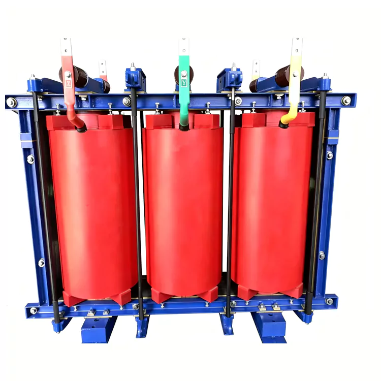
1. Laminated Iron Core with Distributed Air Gaps
The core is assembled from electrical steel laminations with distributed air gaps. The air-gap structure provides the required magnetic reluctance and helps maintain the designed inductance under the specified operating current.
Core clamping and mechanical reinforcement are designed to control vibration and maintain structural stability during normal operation and specified short-circuit conditions.
2. Copper Winding
The winding uses copper conductors selected according to the rated current and thermal requirements of the reactor.
For dry-type construction, the winding can be insulated using a vacuum cast epoxy-resin system. The final winding arrangement depends on the voltage class, current, thermal duty and insulation requirements of the project.
3. Cast-Resin Insulation
The dry-type insulation system provides the electrical insulation between the winding and grounded structural components.
Vacuum casting can reduce voids within the insulation system and provide a rigid mechanical structure. The insulation configuration is determined according to the required insulation level and environmental conditions.
4. Mechanical Support and Vibration Control
The reactor assembly incorporates insulating supports, clamping components and vibration-control elements.
These components are designed to maintain winding and core stability during normal operation and specified transient or short-circuit conditions.
5. Temperature Monitoring and Cooling
Temperature sensors can be provided for monitoring the reactor's operating temperature.
Depending on the rated current and thermal design, the reactor can use natural-air cooling or forced-air cooling. Alarm and fan-control functions can be incorporated where required.
Technical Specifications
The following table provides the main parameters that should be confirmed during technical clarification. Exact values depend on the capacitor bank and power-system design.
|
Parameter |
Specification / Configuration |
|
Product type |
Dry-Type Filter Series Reactor |
|
Reactor function |
Capacitor-bank series reactor / filter reactor |
|
Reactor configuration |
Fixed inductance |
|
Insulation type |
Dry-type cast-resin insulation |
|
Core |
Laminated electrical steel with distributed air gaps |
|
Winding conductor |
Copper |
|
Rated system voltage |
According to project requirements |
|
Rated current |
According to capacitor-bank rating |
|
Rated frequency |
According to system requirements |
|
Rated inductance |
According to filter or detuning design |
|
Reactor percentage |
According to system and capacitor-bank calculation |
|
Target harmonic frequency |
According to filter design, where applicable |
|
Cooling |
Natural air or forced air according to thermal design |
|
Temperature monitoring |
Available according to configuration |
|
Installation |
Indoor or outdoor, subject to environmental design |
|
Insulating oil |
None |
|
Insulation level |
According to rated voltage and applicable standard |
|
Ambient conditions |
To be confirmed according to installation site |
|
High-altitude application |
Available with corresponding design adjustments |
|
Applicable standards |
According to project requirements and applicable IEC/GB standards |
Technical note: Reactor percentage, inductance, current rating and target tuning frequency should not be treated as interchangeable specifications. They need to be calculated together with the capacitor bank and system impedance.
Reactor Percentage and Filter Selection
The reactor percentage is an important parameter when configuring a capacitor-bank filter branch.
It represents the relationship between the reactor's inductive reactance and the capacitor's capacitive reactance at the fundamental frequency. Different reactor percentages produce different resonant characteristics.
For this reason, the reactor should not be selected simply because a particular percentage is commonly used.
The selection normally considers:
· System voltage
· Fundamental frequency
· Capacitor-bank voltage and capacity
· Required reactive power
· Existing harmonic spectrum
· Dominant harmonic orders
· Short-circuit capacity of the grid
· Transformer impedance
· Cable and line characteristics
· Expected capacitor switching frequency
· Required filter performance
· Applicable standards and customer specifications
For projects involving significant harmonic distortion, a harmonic study or power-quality assessment should be completed before finalizing the reactor parameters.
Filter Reactor vs. Detuned Reactor
The terms filter reactor and detuned reactor describe different design objectives and should not be used interchangeably.
|
Item |
Tuned Filter Reactor |
Detuned Series Reactor |
|
Main purpose |
Form a filter branch around a specified harmonic frequency |
Reduce the risk of resonance and harmonic amplification |
|
Capacitor connection |
Series-connected with capacitor bank |
Series-connected with capacitor bank |
|
Reactor selection |
Based on target filter frequency and system conditions |
Based on desired detuning point and system conditions |
|
Harmonic objective |
Provide a defined filtering characteristic |
Move resonance away from problematic harmonic frequencies |
|
System study |
Recommended |
Recommended |
|
Typical application |
Dedicated harmonic filtering |
General capacitor-bank protection and harmonic mitigation |
The final configuration should be selected according to the actual harmonic spectrum and compensation-system design.
Key Design Characteristics
Dry-Type, Oil-Free Construction
The reactor contains no insulating oil. This eliminates oil filling, oil leakage inspection and oil replacement from routine maintenance.
The configuration can be considered for indoor substations and compact capacitor-compensation installations where an oil-free design is preferred.
Fixed Inductance
The reactor provides a predetermined inductance rather than continuously adjustable reactance. Its electrical parameters are selected during the engineering stage based on the required compensation and harmonic-control function.
Capacitor Switching Current Limitation
When a capacitor bank is energized, transient current can occur. The series reactor increases the impedance of the circuit and helps limit the magnitude and rate of the switching current.
The actual limitation effect depends on the capacitor-bank configuration, switching method and system impedance.
Harmonic and Resonance Control
A properly selected series reactor changes the impedance and resonant characteristics of the compensation branch. Depending on the design, it can be used for tuned filtering or detuning.
The reactor itself should not be described as eliminating all harmonics. Its performance depends on the complete capacitor-reactor-system configuration.
Temperature Monitoring
Temperature monitoring can be incorporated into the reactor. For higher-current designs, forced-air cooling and fan-control functions can be provided where required by the thermal calculation.
Typical Applications
The dry-type filter series reactor can be specified for capacitor-based compensation systems in applications such as:
· 10 kV and 35 kV distribution systems
· Indoor substations and switching stations
· Industrial plants and industrial parks
· Mining and heavy industrial power systems
· Capacitor-bank reactive power compensation systems
· Harmonic mitigation installations
· Power-quality improvement projects
· Systems with frequent capacitor switching
· Compact indoor compensation equipment
The appropriate reactor rating should be determined from the electrical characteristics of the complete compensation system.
Selection Information for Buyers
For a project quotation, the following information is useful:
1. System rated voltage
2. System frequency
3. Required reactive power in kvar or Mvar
4. Capacitor-bank rated voltage
5. Capacitor-bank capacity
6. Required reactor percentage or inductance, if already specified
7. Target harmonic order, for tuned filter applications
8. Measured or calculated harmonic spectrum
9. Short-circuit capacity or short-circuit impedance
10. Installation location
11. Ambient temperature and altitude
12. Indoor or outdoor installation
13. Applicable IEC, GB or project-specific standards
14. Required routine, type or special tests
If the reactor percentage or inductance has not yet been determined, the capacitor-bank parameters and available system information can be provided for technical review.
Manufacturing and Testing Capability
The dry-type filter series reactor is manufactured by Jiangshan Yulan Transformer Co., Ltd., established in 1999 in Jiangshan, Zhejiang, China.
Yulan manufactures transformers and reactors up to the 110 kV class. The company occupies approximately 35,000 m², including a 15,000 m² production workshop, and has more than 75 employees, including engineering and technical personnel.
The production and testing facilities include:
· 80-ton lifting equipment
· 400 kW kerosene vapor phase vacuum drying system for 110 kV-class products
· 1200 kV impulse test equipment
· 400 kV power-frequency withstand voltage test equipment
· 300 kV induction test equipment
· Computer-controlled vertical winding equipment
· Core slitting and cross-cutting lines
· Foil winding equipment
· Hydraulic pressing equipment
· Other transformer and reactor production and testing equipment
The available manufacturing and testing facilities allow the reactor configuration and test program to be aligned with the technical requirements of individual projects.
Quality Management and Testing
Jiangshan Yulan Transformer Co., Ltd. operates the following management systems:
· ISO 9001:2015 Quality Management System
· ISO 14001 Environmental Management System
· ISO 45001:2018 Occupational Health and Safety Management System
For reactor projects, the applicable testing requirements are determined by the product design, applicable standard and customer specification.
Where required, the technical documentation can include relevant test reports and factory inspection records.
For export projects, the applicable IEC requirements, destination-market requirements and customer specifications should be confirmed during the technical clarification stage.
Dry-Type vs. Oil-Immersed Series Reactors
The selection between dry-type and oil-immersed construction depends on the rated voltage, current, capacity, installation environment, thermal requirements and project specifications.
|
Item |
Dry-Type Filter Series Reactor |
Oil-Immersed Series Reactor |
|
Insulation medium |
Dry-type insulation / cast resin |
Insulating oil |
|
Oil management |
Not required |
Required |
|
Oil leakage |
No insulating oil |
Applicable |
|
Indoor installation |
Suitable for applicable designs |
Possible with corresponding site provisions |
|
Maintenance |
No routine oil maintenance |
Oil-related maintenance required |
|
Fire-protection requirements |
Generally simpler for applicable installations |
Additional fire and oil-containment provisions may be required |
|
Cooling |
Natural or forced air, according to design |
Oil-based cooling system |
|
Compact installations |
Suitable for applicable designs |
Subject to equipment and oil-containment requirements |
|
High-current / large-capacity applications |
Subject to thermal and mechanical design |
Configuration-dependent |
This comparison is a general engineering reference. Final equipment selection should be based on the project specification and system study.
Technical Documentation
Depending on the project and contract, the supply documentation may include:
· Product technical specification
· General arrangement drawing
· Nameplate information
· Electrical schematic or control wiring diagram, where applicable
· Routine test report
· Factory inspection documentation
· Installation and operation instructions
· Product certificate
· Relevant quality-management certificates
The exact documentation package should be confirmed during quotation and contract review.
Frequently Asked Questions
1. What is a dry-type filter series reactor?
A dry-type filter series reactor is an inductive device connected in series with a capacitor bank. It modifies the impedance of the compensation branch, helps limit capacitor switching current and can be used for harmonic filtering or detuning, depending on the system design.
2. What is the difference between a filter reactor and a shunt reactor?
A shunt reactor is connected in parallel with the power system and is mainly used to absorb capacitive reactive power from lines and cables.
A filter series reactor is connected in series with a capacitor bank. Its main functions include changing the impedance of the compensation branch, limiting switching current and controlling harmonic or resonance characteristics.
3. What does the reactor percentage mean?
The reactor percentage describes the relationship between the reactor's fundamental-frequency reactance and the capacitor's capacitive reactance. It influences the resonant characteristics of the capacitor-reactor branch.
The correct percentage depends on the system and should be determined during engineering design.
4. Can one reactor filter the 3rd, 5th and 7th harmonics at the same time?
Not necessarily. A single tuned filter branch is normally designed around a specified frequency or harmonic range. If multiple harmonic orders need to be addressed, multiple filter branches or a different filtering strategy may be required.
The harmonic spectrum and system impedance should be evaluated before selecting the reactor configuration.
5. Does a series reactor eliminate harmonics?
No. The reactor changes the impedance and frequency characteristics of the capacitor branch. Its effectiveness in harmonic mitigation depends on the complete filter design, including the capacitor, reactor, system impedance and existing harmonic sources.
6. Does the reactor protect capacitors during switching?
A series reactor can help limit capacitor-bank switching inrush current and reduce transient electrical stress. The actual protection effect depends on the capacitor-bank configuration and switching equipment.
7. Can the reactor be used in a 10 kV or 35 kV system?
Yes, dry-type series reactors can be designed for medium-voltage applications such as 10 kV and 35 kV systems. The rated current, insulation level, inductance and reactor percentage must be determined from the specific compensation system.
8. Can the reactor be installed indoors?
Yes. Dry-type construction is suitable for applicable indoor installations. The final design should consider ambient temperature, ventilation, pollution level, insulation requirements, clearances and heat dissipation.
9. Can Yulan manufacture a customized filter reactor?
Yes. Yulan can configure the reactor according to the required voltage, current, inductance, reactor percentage, installation conditions, cooling method and applicable technical standards.
10. What information should I provide for a quotation?
For an initial technical assessment, provide the system voltage, frequency, capacitor-bank capacity, capacitor voltage, required Mvar or kvar, reactor percentage or inductance if known, harmonic information and installation conditions.
If the reactor parameters have not yet been determined, a single-line diagram and capacitor-bank information can be provided for technical review.
Related Category
Send Inquiry
Contact Info
-
Address
No. 20, Bai'e Road, Hecun Town, Jiangshan City, Zhejiang Province,CHINA
-
Tel
-
Email
Send specs for power, furnace or rectifier transformers and get a customized quotation and price list, direct from Yulan Transformer factory. Bulk orders welcome.
Related Products
News Recommendations




