
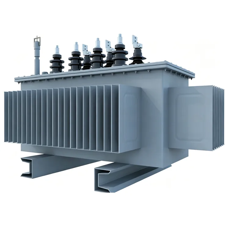
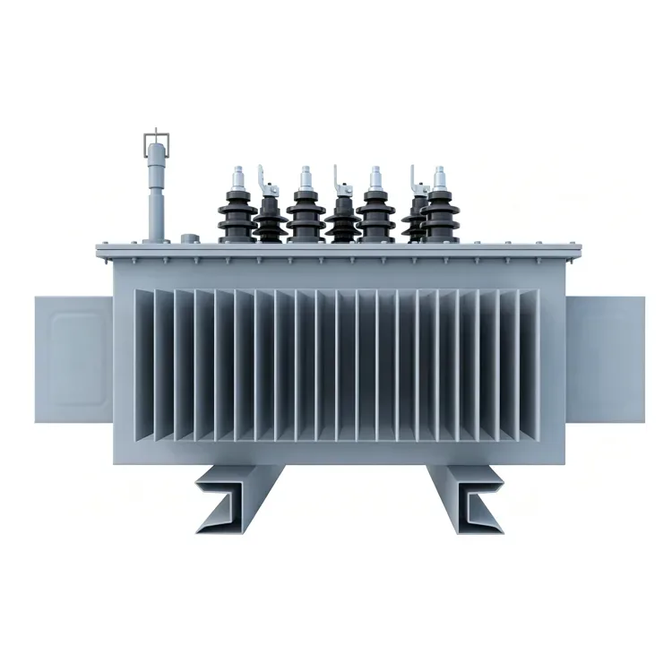
10kV Amorphous Alloy Oil-Immersed Distribution Transformer
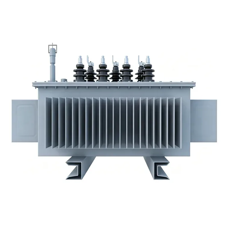
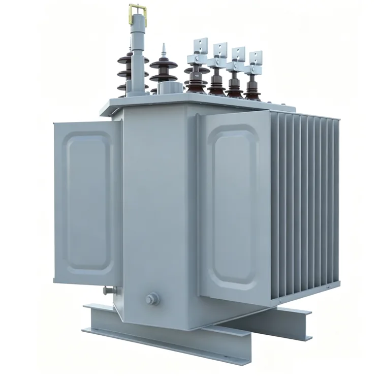
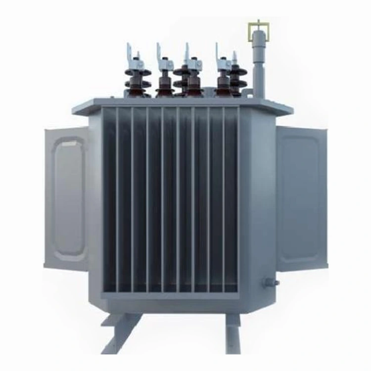
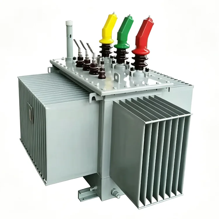
Yulan Transformer’s 10KV Amorphous alloy oil-immersed distribution Transformer covers 30‑2500kVA, supporting 6kV/10kV/35kV primary and 0.4kV secondary voltage, compliant with IEC, GB, ANSI/IEEE, NEMA standards. All units pass complete routine tests under ISO‑certified production, with off‑circuit tap‑changing, ONAN cooling and traceable batch records for reliable field deployment.
Distribution transformers serving rural power grids and certain industrial users often operate under light-load conditions for extended periods, where no-load losses frequently account for a larger share of total losses than load losses. Amorphous alloy cores offer distinct energy-saving advantages in such operating scenarios. Yulan Transformer utilizes amorphous alloy materials in its 10KV Amorphous alloy oil-immersed distribution Transformers, which range in capacity from 30kVA to 2500kVA; these units support primary voltages of 6kV, 10kV, or 35kV and a secondary output of 0.4kV. Production and testing adhere to the same rigorous processes and standards used for the company's 110kV-class transformers, with key steps including core-and-coil assembly drying, insulation treatment, and factory-acceptance loss verification.
Material and Energy Efficiency Characteristics
The no-load loss of amorphous alloy strip is approximately one-third to one-fifth that of cold-rolled grain-oriented silicon steel sheets of the same specifications, and its coercivity is significantly lower. This results in reduced active power consumption and lower exciting current during no-load or light-load operation. Energy-saving benefits are particularly pronounced at sites with an annual load factor of less than 30%.
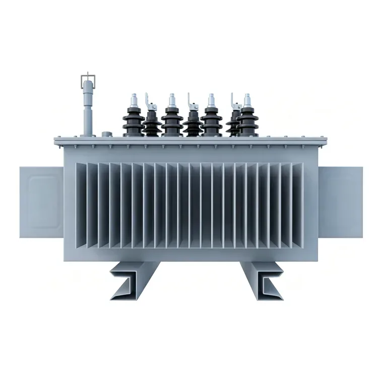
The core features a three-phase, five-limb wound structure that ensures a continuous magnetic circuit and fewer joints compared to stacked cores. A formed thin-plate frame is used for clamping, which minimizes vibrational displacement of the strip during operation and helps maintain stable core performance. As amorphous alloys are sensitive to mechanical stress, the manufacturing process involves strict controls on winding tension and assembly pressure.
Comparison with silicon steel sheet transformers
|
Comparison Item |
Amorphous alloy core transformer |
Cold-rolled silicon steel sheet transformer |
|
No-load loss |
Approximately 1/3 to 1/5 that of silicon steel sheets |
Relatively high |
|
Load loss |
Comparable; difference is minimal |
The two are similar; the difference is small |
|
Volume and weight |
Usually slightly larger for the same capacity |
Relatively compact |
|
Material cost |
Slightly higher |
Slightly lower |
|
Applicable load factor |
Sites operating below 50% load for extended periods |
Medium-to-high load factors or space-constrained applications |
|
Noise |
No-load noise is slightly higher; controllable through structural design |
Slightly lower no-load noise |
Coil and Assembly
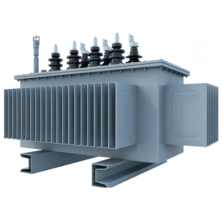
The low-voltage coils are wound using copper foil, while the high-voltage coils are formed using adhesive-coated paper that is heat-cured under pressure; both types possess high mechanical strength and can withstand short-circuit electromagnetic forces. Following assembly, the active part undergoes processing in a kerosene vapor-phase vacuum drying system to remove moisture and gases from the insulation materials. The tank and external structural components undergo shot-blasting for rust removal followed by electrostatic powder coating, ensuring coating uniformity and adhesion that meet the requirements for outdoor operation.
Key Specifications
|
Item |
Standards |
|
Executive Standard |
IEC, GB, ANSI/IEEE, NEMA |
|
Rated Capacity |
30 kVA to 2500 kVA |
|
Primary Rated Voltage |
6 kV, 10 kV, 35 kV (depending on specific model) |
|
Secondary Rated Voltage |
0.4 kV |
|
Number of Taps |
5 taps (off-circuit tap changing) |
|
Rated Frequency |
50 Hz / 60 Hz |
|
Number of Phases |
Three-phase |
|
Vector Group |
Dyn11, Yyn0, etc. |
|
Short-circuit Impedance |
4.0% / 4.5% / 6.0% / 6.5% (varies by capacity range) |
|
Cooling Method |
ONAN (Oil-immersed natural cooling) |
|
Voltage Regulation Method |
Off-circuit tap changing |
Reference Data for Losses
The following data represent typical values under Grade 1 energy efficiency conditions, derived from factory test records of batch-produced units.
|
Rated capacity KVA |
Level 1 |
Level2 |
Level3 |
Short-circuit impedance % |
||||||
|
Amorphous alloy |
Amorphous alloy |
Amorphous alloy |
||||||||
|
No-load loss W |
Load loss W |
No-load lossW |
Load loss W |
No-load loss W |
Load loss
|
|||||
|
Dyn11/Yzn11 |
Yyn0 |
Dyn11/Yzn11 |
Yyn0 |
Dyn11/Yzn11 |
Yyn0 |
|||||
|
30 |
25 |
510 |
480 |
33 |
535 |
510 |
33 |
630 |
500 |
4.0 |
|
50 |
35 |
735 |
700 |
43 |
780 |
745 |
43 |
910 |
8700 |
|
|
63 |
40 |
880 |
840 |
50 |
930 |
890 |
50 |
1090 |
1040 |
|
|
80 |
50 |
1060 |
1010 |
60 |
1120 |
1070 |
60 |
1310 |
1250 |
|
|
100 |
60 |
1270 |
1215 |
75 |
1350 |
1285 |
75 |
1580 |
1500 |
|
|
125 |
70 |
1530 |
1450 |
85 |
1615 |
1540 |
85 |
1890 |
1800 |
|
|
160 |
80 |
1870 |
1780 |
100 |
1970 |
1880 |
100 |
2310 |
2200 |
|
|
200 |
95 |
2210 |
2100 |
120 |
2330 |
2225 |
120 |
2730 |
2600 |
|
|
250 |
110 |
2590 |
2470 |
140 |
2735 |
2640 |
140 |
3200 |
3050 |
|
|
345 |
135 |
3100 |
2950 |
170 |
3275 |
3120 |
170 |
3830 |
3650 |
|
|
400 |
160 |
3660 |
3480 |
200 |
3865 |
3675 |
200 |
4520 |
4300 |
|
|
500 |
190 |
4380 |
4170 |
240 |
4625 |
4400 |
240 |
5410 |
5150 |
|
|
630 |
250 |
5020 |
320 |
5300 |
320 |
6200 |
4.5 |
|||
|
800 |
300 |
6075 |
380 |
5415 |
380 |
7500 |
||||
|
1000 |
360 |
8340 |
450 |
8800 |
450 |
10300 |
||||
|
1250 |
425 |
9720 |
530 |
10260 |
530 |
12000 |
||||
|
1600 |
500 |
11745 |
630 |
12400 |
630 |
14500 |
||||
|
2000 |
550 |
14000 |
710 |
14800 |
720 |
18300 |
5.0 |
|||
|
2500 |
670 |
15450 |
860 |
16300 |
865 |
21200 |
||||
Note: Final data is subject to the technical agreement for the order; load losses may vary slightly depending on the vector group.
Manufacturing and Verification
Before leaving the factory, each unit undergoes routine tests, including winding DC resistance, voltage ratio, insulation resistance, power-frequency withstand voltage, induced withstand voltage, no-load loss, load loss, and short-circuit impedance. Test data is archived by serial number, ensuring traceability to specific manufacturing processes and material batches. The company holds ISO 9001:2015, ISO 14001, and ISO 45001 certifications.
Selection and Operation Q&A
Q: How do I determine if my site is suitable for an amorphous alloy transformer?
You can review load records from the past year. If the average annual load factor is below 30%, or if the transformer remains energized for long periods with low actual power consumption, the amorphous alloy solution typically offers cost advantages regarding electricity bills. For users with a load factor consistently exceeding 50%, a silicon steel transformer may offer a lower total cost of ownership.
Q: How is the batch-to-batch consistency of amorphous alloy materials ensured?
The strip material is sourced primarily from domestic manufacturers capable of mass supply; upon arrival, samples from each batch are tested for magnetic properties and thickness deviation. Winding and annealing processes follow fixed parameters, and finished-product no-load loss data is linked to the material batch, allowing for rapid identification of issues should anomalies occur.
Q: How is the full life-cycle cost calculated?
In addition to the equipment purchase price, the cost of energy loss during operation must be considered. While amorphous alloy transformers have a slightly higher initial cost, their low no-load loss means that, in low-load scenarios, the electricity savings over a few years can offset the price difference. The specific payback period depends on local electricity rates and load profiles; the technical department can perform a dedicated analysis.
Q: Is the noise level higher than that of silicon steel transformers?
It is indeed slightly higher in the no-load state because amorphous alloys have a higher magnetostriction coefficient. However, through the use of core clamping structures, rigid tank designs, and sound insulation measures, noise levels can be kept within the limits stipulated by the State Grid and China Southern Power Grid. Actual values vary based on capacity and installation conditions; measurement standards can be specified in the contract.
Q: What precautions should be taken during installation and transport?
The unit must be kept upright. When lifting, use the designated lifting points on the top of the tank; ensure that steel cables do not come into contact with the radiators or bushings. Amorphous alloy cores are sensitive to impact, so severe jolting and sudden braking should be avoided during transport. Upon arrival, it is recommended to allow the unit to settle before inspecting the oil level, seals, and pressure relief device, and subsequently conducting handover tests.
Typical Application Scenarios
Common installation sites for amorphous alloy transformers include rural distribution substations, power supply lines in mountainous areas, distribution rooms in residential complexes, facilities for small industrial users, and auxiliary power distribution systems for new energy power plants. For sites characterized by long annual operating hours and low average load rates, the reduction in no-load losses translates into direct savings in operating costs.
Related Category
Send Inquiry
Contact Info
-
Address
No. 20, Bai'e Road, Hecun Town, Jiangshan City, Zhejiang Province,CHINA
-
Tel
-
Email
Send specs for power, furnace or rectifier transformers and get a customized quotation and price list, direct from Yulan Transformer factory. Bulk orders welcome.
Related Products
News Recommendations




