
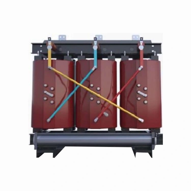
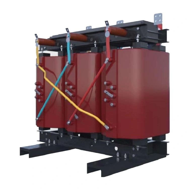
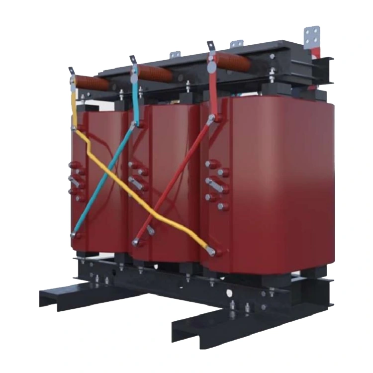
Epoxy Resin Cast Dry-Type Power Transformer
Yulan Transformer’s Epoxy Resin Cast Dry-Type Power Transformers are specifically designed for buildings, airports, tunnels, chemical plants, and other locations with strict fire safety requirements, ensuring safe and reliable power distribution. This product series offers capacities ranging from 30 to 2,500 kVA, with input voltage options of 6 kV, 10 kV, or 35 kV. As an experienced manufacturer and supplier, Yulan Transformer provides customized configuration solutions.
The 10kV Epoxy Resin Cast Dry-Type Power Transformer is a standard power distribution unit for facilities with strict fire and explosion protection requirements, such as high-rise buildings, commercial centers, airports, tunnels, chemical plants, and auxiliary systems for nuclear power stations. Manufactured by Yulan Transformer, this series offers capacities ranging from 30kVA to 2500kVA, with primary voltage options of 6kV, 10kV, or 35kV and a secondary output of 0.4kV. Production leverages the company's 110kV-class manufacturing and testing capabilities, featuring key processes such as vacuum casting, curing, and partial discharge testing.
Application Environments
These Epoxy Resin Cast Dry-Type Power Transformers are primarily designed for indoor power distribution systems but can also be installed outdoors within protective enclosures. Common applications include:
● Power distribution rooms in high-rise buildings and commercial complexes
● Lighting and power supply systems for airports and rail transit stations
● Ventilation, drainage, and monitoring systems for tunnels
● Areas with stringent fire safety requirements, such as chemical and pharmaceutical plants
● Auxiliary facilities for nuclear power stations and backup power for data centers
Users may opt for enclosures with IP20, IP23, or higher protection ratings based on site conditions.
Technical Features
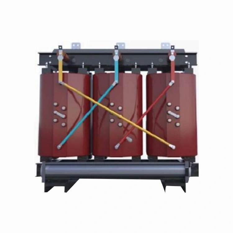
● Low Loss: No-load and load losses comply with the energy efficiency requirements of GB 20052-2020
● Low Noise: Meets domestic grid company noise standards for dry-type transformers
● Low Partial Discharge: Factory-tested partial discharge levels are controlled below 5pC
● High Mechanical Strength: The cured epoxy resin forms a dense insulation layer capable of withstanding electromagnetic forces during short-circuit events
● Selectable Insulation Classes: Available in three temperature rise classes—Class B (100°C), Class F (120°C), and Class H (145°C)
Technical Specifications
|
Item |
Standards |
|
Executive Standard |
IEC, GB, ANSI/IEEE, NEMA |
|
Rated Capacity |
30 kVA to 2500 kVA |
|
Primary Rated Voltage |
6 kV, 10 kV, 35 kV (depending on model) |
|
Secondary Rated Voltage |
0.4 kV |
|
Number of Taps |
5 taps (off-circuit tap changing) |
|
Rated Frequency |
50 Hz / 60 Hz |
|
Number of Phases |
Three-phase |
|
Vector Group |
Dyn11, Yyn0, etc. |
|
Short-circuit Impedance |
4.0% / 6.0% (varies by capacity) |
|
Insulation Class |
Class B, F, or H (optional) |
|
Cooling Method |
AN or AF |
|
Protective Enclosure |
Optional; customizable IP rating |
Energy Efficiency Ratings and Loss Parameters
The table below lists the no-load losses and Class F (120°C) load losses for various capacities across three energy efficiency levels. Data for Class B and Class H load losses can be obtained from the technical department. The values in the table are based on electrical steel strip cores and an automated lamination process, complying with the energy efficiency requirements of GB 20052-2020.
|
Rated capacity KVA |
Level 1 |
Level2 |
Level3 |
Short-circuit impedance % |
|||||||||
|
Electrical steel strip |
Electrical steel strip |
Electrical steel strip |
|||||||||||
|
No-load loss W |
Load loss W |
No-load loss w |
Load loss W |
No-load loss W |
Load loss W |
||||||||
|
B (100℃) |
F (120℃) |
H (145℃) |
B (100℃) |
F (120℃) |
H (145℃) |
B (100℃) |
F (120℃) |
H (145℃) |
|||||
|
30 |
105 |
605 |
640 |
685 |
130 |
605 |
640 |
685 |
150 |
670 |
710 |
760 |
4.0 |
|
50 |
155 |
845 |
900 |
965 |
185 |
845 |
900 |
965 |
215 |
940 |
1000 |
1070 |
|
|
80 |
210 |
1160 |
1240 |
1330 |
250 |
1160 |
1240 |
1330 |
295 |
1290 |
1380 |
1480 |
|
|
100 |
230 |
1330 |
1415 |
1520 |
270 |
1330 |
1415 |
1520 |
320 |
1480 |
1570 |
1690 |
|
|
125 |
270 |
1565 |
1665 |
1780 |
320 |
1565 |
1665 |
1780 |
375 |
1740 |
1850 |
1980 |
|
|
160 |
310 |
1800 |
1915 |
2050 |
365 |
1800 |
1915 |
2050 |
430 |
2000 |
2130 |
2280 |
|
|
200 |
360 |
2135 |
2275 |
2440 |
420 |
2135 |
2275 |
2440 |
495 |
2370 |
2530 |
2710 |
|
|
250 |
415 |
2330 |
2485 |
2665 |
490 |
2330 |
2485 |
2665 |
575 |
2590 |
2760 |
2960 |
|
|
345 |
510 |
2945 |
3125 |
3355 |
600 |
2945 |
3125 |
3355 |
705 |
3270 |
3470 |
3730 |
|
|
400 |
570 |
3375 |
3590 |
3850 |
665 |
3375 |
3590 |
3850 |
785 |
3750 |
3990 |
4280 |
|
|
500 |
670 |
4130 |
4390 |
4705 |
790 |
4130 |
4390 |
4705 |
930 |
4890 |
4880 |
5230 |
|
|
630 |
775 |
4975 |
5290 |
5660 |
910 |
4975 |
5290 |
5660 |
1070 |
5530 |
5880 |
6290 |
|
|
630 |
750 |
5050 |
5365 |
5760 |
885 |
5050 |
5365 |
5760 |
1040 |
5610 |
5960 |
6400 |
6.0 |
|
800 |
875 |
5895 |
6265 |
6715 |
1035 |
5895 |
6265 |
6715 |
1215 |
6550 |
6960 |
7490 |
|
|
1000 |
1020 |
6885 |
7315 |
7885 |
1205 |
6885 |
7315 |
7885 |
1415 |
7650 |
8130 |
8760 |
|
|
1250 |
1205 |
8190 |
8720 |
9335 |
1420 |
8190 |
8720 |
9335 |
16770 |
9100 |
9690 |
10370 |
|
|
1600 |
1415 |
9945 |
10555 |
11320 |
1665 |
9945 |
1055 |
11320 |
1960 |
11050 |
11730 |
12580 |
|
|
2000 |
1760 |
12240 |
13005 |
14005 |
2075 |
12240 |
13005 |
14005 |
2440 |
13600 |
14450 |
15560 |
|
|
2500 |
2080 |
14535 |
15445 |
16605 |
2450 |
14535 |
15445 |
16605 |
2880 |
16150 |
17170 |
18450 |
|
Note: Load losses for Class B (100 ° C) are approximately 5% – 8% lower than those for Class F, while those for Class H (145 ° C) are approximately 6% – 9% higher. Final specifications are subject to the technical agreement at the time of order.
Manufacturing and Quality Control
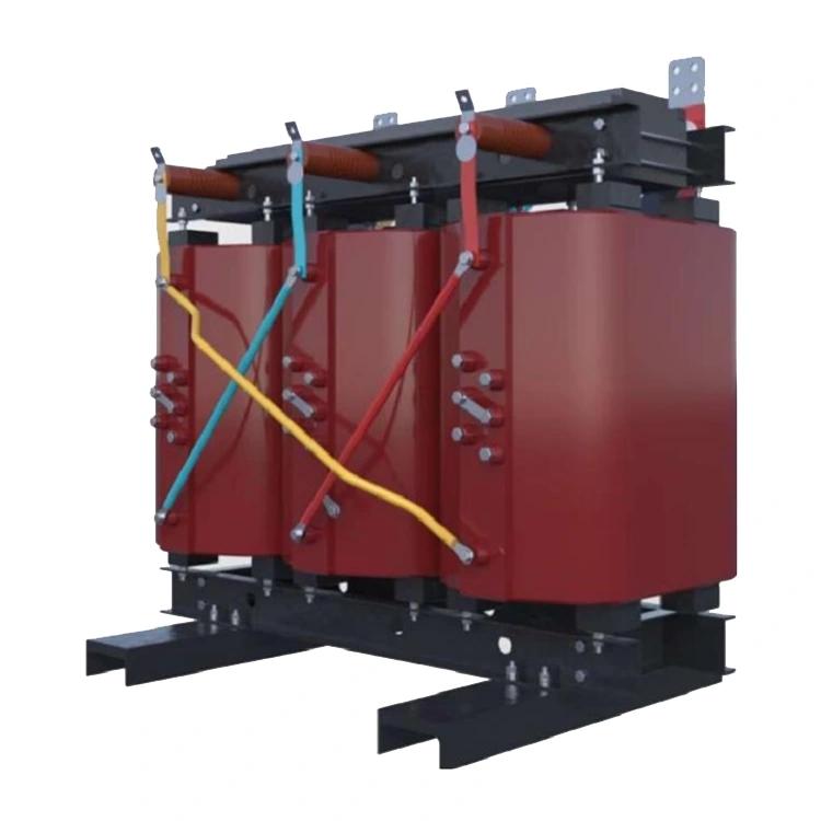
The core utilizes cold-rolled grain-oriented silicon steel sheets, stacked using fully automated equipment; burr dimensions and lamination factors are strictly controlled, resulting in no-load losses that are 5% – 10% lower than those of manually stacked cores. High- and low-voltage windings are cast in epoxy resin under vacuum conditions, forming an integral insulation structure after curing, with a partial discharge level not exceeding 5 pC. Insulation class is selected based on load profiles and ambient temperature, while the enclosure protection rating is determined by the installation site.
Before leaving the factory, each unit undergoes testing for winding DC resistance, voltage ratio, insulation resistance, power-frequency withstand voltage, induced withstand voltage, no-load loss, load loss, short-circuit impedance, and partial discharge. The company holds ISO 9001:2015, ISO 14001, and ISO 45001 certifications.
Selection and Installation Q&A
Q: Is a protective enclosure required?
If installed in a dedicated electrical room with restricted access, an enclosure is not required. For installations in public areas, corridors, or equipment rooms, an enclosure with an IP20 rating or higher is recommended to prevent foreign objects from contacting live parts. Outdoor use requires an IP23 rating or higher, and derating due to ventilation conditions must be considered.
Q: How do I choose between Class B, F, and H insulation?
Class B is suitable for standard electrical rooms with lower ambient temperatures and stable loads. Class F is the current standard, offering a balance between cost and overload capability. Class H is suitable for operating conditions involving higher ambient temperatures or frequent short-term overloads. Temperature rise limits and enclosure ventilation conditions must be verified during selection.
Q: Can it be used in a 60Hz system?
Yes. The core magnetic flux density and winding parameters are designed for 60Hz operation, and loss and temperature rise values are verified at the corresponding frequency before shipment.
Q: What does a partial discharge level of less than 5 pC signify?
This indicates minimal internal air bubbles and impurities within the cast insulation, resulting in a dense, high-quality insulating structure. Low partial discharge levels during long-term operation help mitigate the risks of insulation aging and sudden failure, making these transformers particularly suitable for applications requiring high power supply continuity.
Q: Can dry-type transformers replace oil-immersed transformers?
The two types are suited to different conditions. Dry-type transformers contain no oil and offer excellent fire resistance, making them ideal for indoor use and densely populated areas. Oil-immersed transformers possess superior overload capacity and generally offer lower costs and smaller footprints for the same capacity, making them suitable for outdoor locations or standalone substations. Selection should be based on a comprehensive assessment of the installation site, fire safety requirements, and operation and maintenance conditions.
Installation and Operation Tips
Dry-type transformers should be installed in well-ventilated areas free from corrosive gases and conductive dust. When operating with an enclosure, ensure that air inlets and outlets remain unobstructed. Before restarting the transformer after a prolonged shutdown, it is recommended to check the insulation resistance and verify that the ventilation system is functioning correctly. For installations in high-humidity or coastal regions, anti-rust treatment may be applied to the transformer core and external metal components.
Please contact the Yulan Transformer sales or technical department for dimensional drawings, installation foundation plans, or information regarding enclosure selection.
Related Category
Send Inquiry
Contact Info
-
Address
No. 20, Bai'e Road, Hecun Town, Jiangshan City, Zhejiang Province,CHINA
-
Tel
-
Email
Send specs for power, furnace or rectifier transformers and get a customized quotation and price list, direct from Yulan Transformer factory. Bulk orders welcome.
Related Products
News Recommendations




