
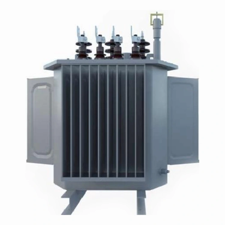
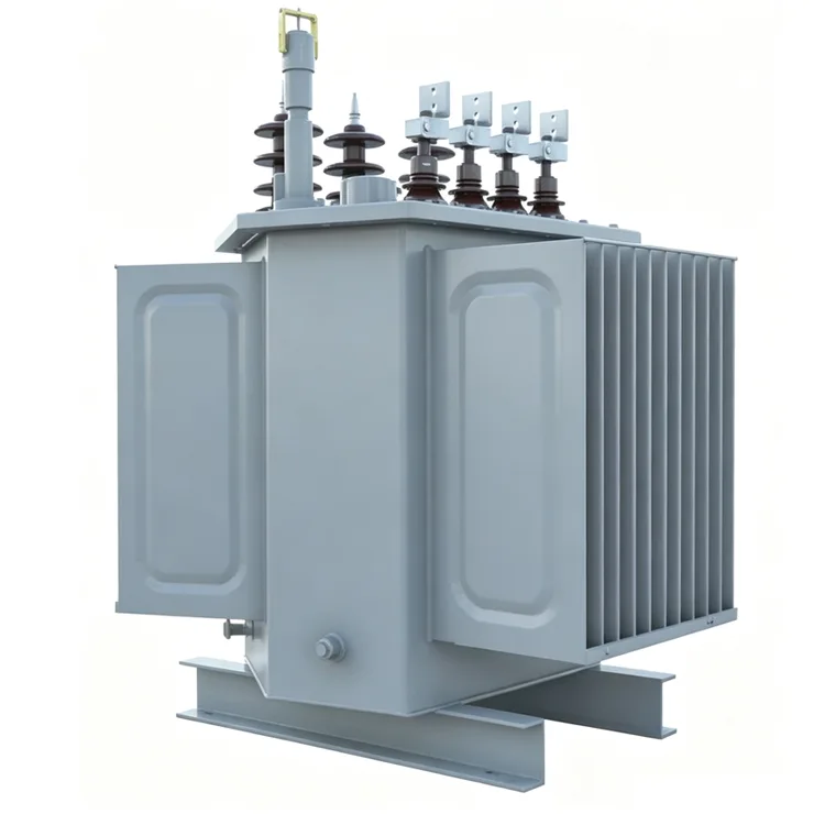
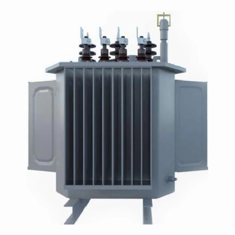
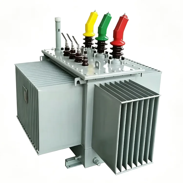
Oil-Immersed Three-Dimensional Wound Core Distribution Transformer
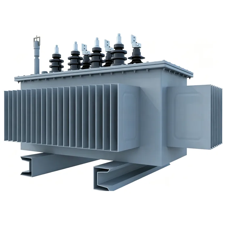
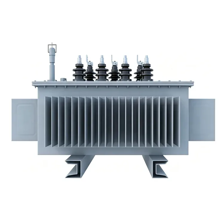
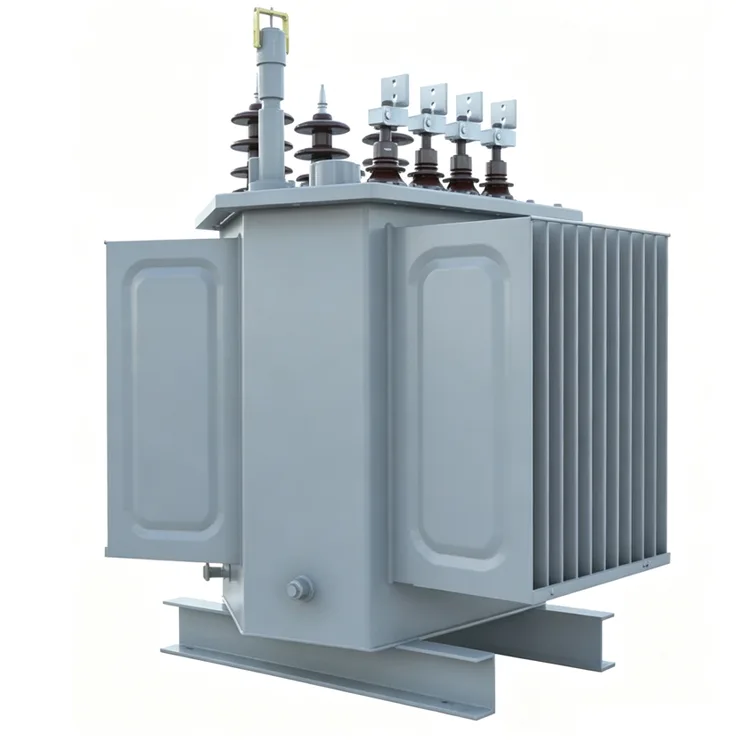
Yulan Oil-Immersed Three-Dimensional Wound Core Distribution Transformers adopt advanced three‑dimensional wound core construction. Covering rated capacities from 30 kVA up to 2500 kVA, the units support primary input voltages of 6 kV, 10 kV and 35 kV, paired with a 0.4 kV secondary output. Feel free to reach out for product enquiries, quotation comparisons and purchase orders.
In distribution transformers, the 3D wound core structure represents an improvement over the traditional planar stacked core design. Yulan Transformer manufactures this Oil-Immersed Three-Dimensional Wound Core Distribution Transformers with capacities ranging from 30 kVA to 2,500 kVA; primary voltage options include 6 kV, 10 kV, or 35 kV, with a secondary output of 0.4 kV. The products comply with relevant IEC, GB, ANSI/IEEE, and NEMA standards, and are manufactured and tested under conditions equivalent to those for 110 kV class transformers.
Structural and Loss Characteristics
The three-phase magnetic circuit is formed by winding continuous strips of silicon steel, resulting in a joint-free magnetic path. The direction of magnetic flux aligns closely with the orientation of the silicon steel, leading to significant reductions in no-load loss, no-load current, and noise levels. The three-phase magnetic paths are equal in length and highly symmetrical, resulting in lower phase-to-phase no-load current imbalance compared to traditional stacked core structures.
The core utilizes cold-rolled grain-oriented silicon steel, with winding and annealing processes carried out according to precise parameters. As there is no need for the overlapping joints found in traditional stacked cores, material utilization is improved; consequently, for a given capacity, the unit's volume and weight are generally lower than those of planar stacked core designs.
Key Technical Parameters
|
Item |
Standards |
|
Executive Standard |
IEC, GB, ANSI/IEEE, NEMA |
|
Rated Capacity |
30 kVA to 2500 kVA |
|
Primary Rated Voltage |
6 kV, 10 kV, 35 kV (depending on specific model) |
|
Secondary Rated Voltage |
0.4 kV |
|
Number of Taps |
5 taps (off-circuit tap changing) |
|
Rated Frequency |
50 Hz / 60 Hz |
|
Number of Phases |
Three-phase |
|
Vector Group |
Dyn11, Yyn0, etc. |
|
Short-circuit Impedance |
4.0% / 4.5% / 6.0% / 6.5% (varies by capacity range) |
|
Cooling Method |
ONAN (Oil-immersed natural cooling) |
|
Insulation Class |
Class A (Oil-immersed type) |
|
Voltage Regulation Method |
Off-circuit tap changing |
Energy Efficiency and Loss Data
The following data is based on cores made of electrical steel strip and batch test results, complying with the energy efficiency limit values specified in GB 20052-2020. Specific loss parameters can be obtained from the technical department based on the capacity range, or estimated by referencing the energy efficiency data for products of the same capacity using planar stacked cores; the no-load loss of the 3D wound core structure is typically 10% to 20% lower.
|
Rated capacity |
Level 1 |
Level2 |
Level3 |
Short-circuit impedance% |
|||||||||||||||
|
Electrical steel strip |
Amorphous alloy |
Electrical steel strip |
Amorphous alloy |
Electrical steel strip |
Amorphous alloy |
||||||||||||||
|
No-load loss W |
Load loss W |
No-load loss
W |
Load loss W |
No-load loss W |
Load loss W |
No-load loss W |
Load lossW |
No-load loss W |
Load loss W |
No-load loss W |
Load loss W |
||||||||
|
Dyn11/Yzn1 |
Yyn0 |
Dyn11/Yzn1 Yyn0 |
Dyn11/Yzn1 Yyn0 |
yn11/Yzn11 |
Yyn0 |
Dyn11/ 1 Yyn0 |
Dyn11/Yzn1 |
Yyn0 |
|||||||||||
|
30 |
65 |
455 |
430 |
25 |
510 |
480 |
70 |
505 |
480 |
33 |
535 |
510 |
80 |
630 |
600 |
33 |
630 |
600 |
4.0 |
|
50 |
80 |
655 |
625 |
35 |
735 |
700 |
90 |
730 |
695 |
43 |
780 |
745 |
100 |
910 |
870 |
43 |
910 |
8700 |
|
|
63 |
90 |
785 |
745 |
40 |
880 |
840 |
100 |
870 |
830 |
50 |
930 |
890 |
110 |
1090 |
1040 |
50 |
1090 |
1040 |
|
|
80 |
105 |
945 |
900 |
50 |
1060 |
1010 |
115 |
1050 |
1000 |
60 |
1120 |
1070 |
130 |
1310 |
1250 |
60 |
1310 |
1250 |
|
|
100 |
120 |
1140 |
1080 |
60 |
1270 |
1215 |
135 |
1265 |
1200 |
75 |
1350 |
|
150 |
1580 |
1500 |
75 |
1580 |
1500 |
|
|
125 |
135 |
1360 |
1295 |
70 |
1530 |
1450 |
150 |
1510 |
1440 |
85 |
1615 |
1540 |
170 |
1890 |
1800 |
85 |
1890 |
1800 |
|
|
160 |
160 |
1665 |
1585 |
80 |
1870 |
1780 |
180 |
185C |
1760 |
100 |
1970 |
1880 |
200 |
2310 |
2200 |
100 |
2310 |
2200 |
|
|
200 |
190 |
1970 |
1870 |
95 |
2210 |
2100 |
215 |
2185 |
2080 |
120 |
2330 |
2225 |
240 |
2730 |
2600 |
120 |
2730 |
2600 |
|
|
250 |
230 |
2300 |
2195 |
110 |
2590 |
2470 |
260 |
2560 |
2440 |
140 |
2735 |
2640 |
290 |
3200 |
3050 |
140 |
3200 |
3050 |
|
|
345 |
270 |
2760 |
2630 |
135 |
310C |
2950 |
305 |
3065 |
2920 |
170 |
3275 |
3120 |
340 |
3830 |
3650 |
170 |
3830 |
3650 |
|
|
400 |
330 |
3250 |
3095 |
160 |
3660 |
3480 |
370 |
3615 |
3440 |
200 |
3865 |
3675 |
410 |
4520 |
4300 |
200 |
4520 |
4300 |
|
|
500 |
385 |
3900 |
3710 |
190 |
4380 |
4170 |
430 |
4330 |
4120 |
240 |
4625 |
4400 |
480 |
5410 |
5150 |
240 |
5410 |
5150 |
|
|
630 |
460 |
4460 |
250 |
5020 |
510 |
4960 |
320 |
5300 |
570 |
6200 |
20 |
6200 |
4.5 |
||||||
|
800 |
560 |
5400 |
300 |
6075 |
630 |
6000 |
380 |
5415 |
700 |
7500 |
380 |
7500 |
|||||||
|
1000 |
665 |
7415 |
360 |
8340 |
845 |
8240 |
450 |
8800 |
830 |
10300 |
450 |
10300 |
|||||||
|
1250 |
780 |
8640 |
425 |
9720 |
870 |
9600 |
530 |
10260 |
970 |
12000 |
530 |
12000 |
|||||||
|
1600 |
940 |
10440 |
500 |
11745 |
050 |
11600 |
630 |
12400 |
1170 |
14500 |
630 |
14500 |
|||||||
|
2000 |
1085 |
13180 |
550 |
14000 |
1225 |
4640 |
710 |
14800 |
360 |
18300 |
720 |
18300 |
5.0 |
||||||
|
2500 |
1280 |
13360 |
670 |
15450 |
1440 |
14840 |
860 |
16300 |
1600 |
21200 |
|
|
|
||||||
Coils and Assembly
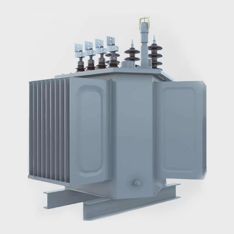
Low-voltage coils are wound using copper foil, while high-voltage coils are formed using adhesive-coated paper, followed by heat-curing under pressure. After assembly, the active part undergoes treatment in a kerosene vapor phase vacuum drying system to remove moisture and gases from the insulation materials. The tank and external structural components are treated via shot-blasting for rust removal and finished with electrostatic powder coating; the coating uniformity and adhesion meet the requirements for outdoor use.
Quality Assurance and Testing
Before leaving the factory, every Oil-Immersed Three-Dimensional Wound Core Distribution Transformer undergoes routine tests, including winding DC resistance, voltage ratio, insulation resistance, power-frequency withstand voltage, induced withstand voltage, no-load loss, load loss, and short-circuit impedance. The company holds ISO 9001:2015, ISO 14001, and ISO 45001 certifications.
FAQs on Model Selection
Q: How do I choose between 3D wound-core and stacked-core transformers?
If there are strict requirements regarding no-load loss, noise levels, or installation space, the 3D wound-core structure offers distinct advantages. While there is little difference in load loss between the two, the manufacturing process for 3D wound cores is more complex, which may result in slightly longer lead times for small-batch orders.
Q: Is the 3D wound-core structure suitable for on-load tap changing?
Yes, though it requires a redesign of the tap lead layout and the internal tank space. Standard products feature off-circuit tap changing; on-load tap changing capabilities must be confirmed at the time of ordering.
Q: What are the requirements for the silicon steel sheets used in this structure?
Grain-oriented silicon steel sheets suitable for winding processes are required, as the annealing process directly impacts the recovery of magnetic properties. Yulan Transformer utilizes material sources with consistent batch quality and controls the post-winding annealing process according to a fixed temperature curve.
Q: How low can the noise level be?
Compared to stacked-core products of the same capacity, noise levels are typically reduced by 3 to 5 dB. Specific values depend on capacity, cooling method, and installation environment; measurement methods can be specified in the contract.
Application Scenarios
These products are suitable for urban and rural grid upgrades, power distribution for industrial and mining enterprises, commercial buildings, and step-up or step-down applications in new energy generation. The low-noise characteristics of the 3D wound-core structure are particularly valuable for noise-sensitive locations, such as distribution substations in residential areas and indoor substations.
Please contact the Yulan Transformer sales or technical department for specific model dimensions, weights, or foundation installation drawings.
Related Category
Send Inquiry
Contact Info
-
Address
No. 20, Bai'e Road, Hecun Town, Jiangshan City, Zhejiang Province,CHINA
-
Tel
-
Email
Send specs for power, furnace or rectifier transformers and get a customized quotation and price list, direct from Yulan Transformer factory. Bulk orders welcome.
Related Products
News Recommendations




