
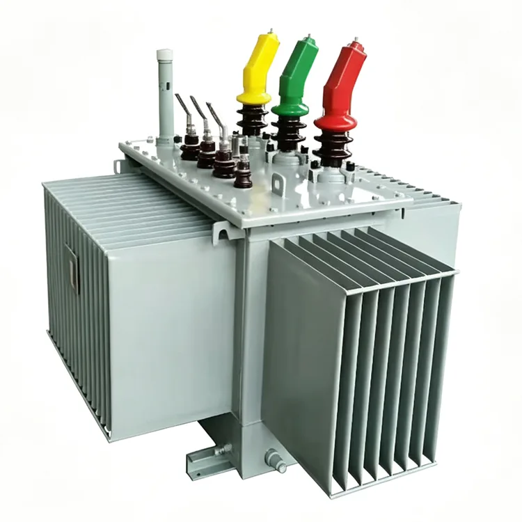
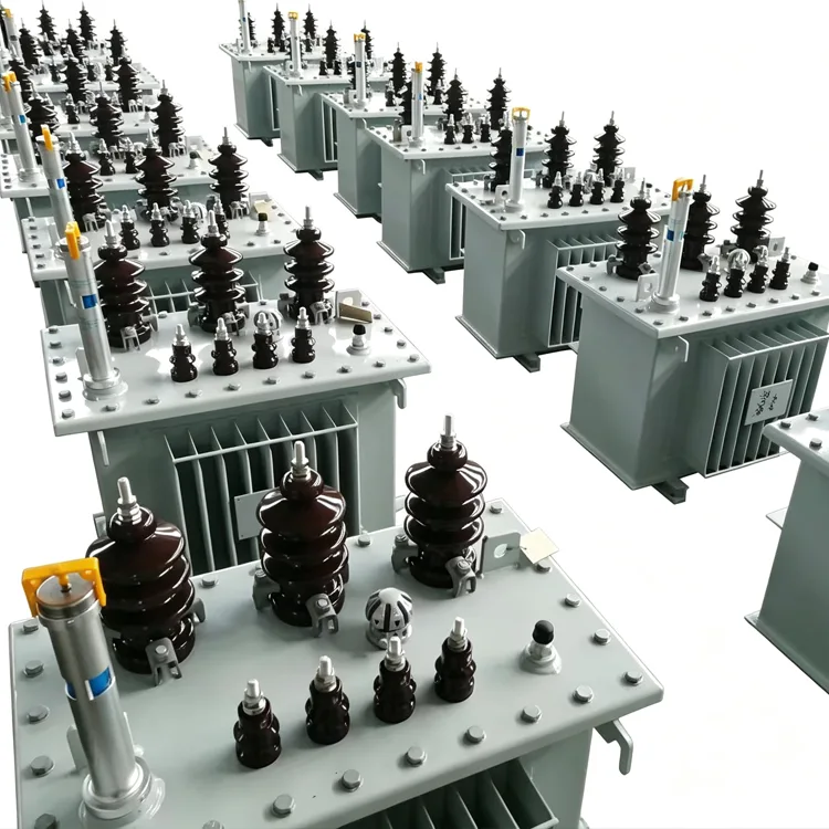
10kV Oil-Immersed Distribution Transformer
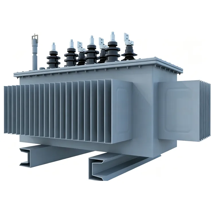
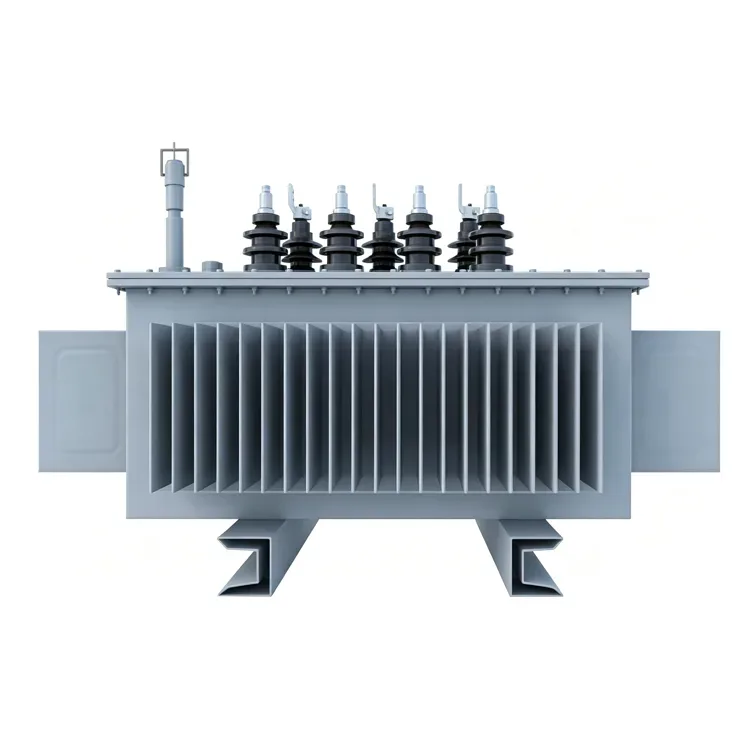
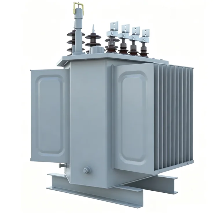
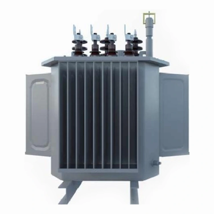
Yulan Transformer 10kV Oil-Immersed Distribution Transformer is designed for urban and rural power distribution networks, covering 30kVA to 2500kVA. Featuring automated core stacking, low loss performance and reliable insulation design, it supports customers to source, purchase and customize efficient transformer solutions for industrial, commercial and utility applications.
The 10kV Oil-Immersed Distribution Transformer is a core product series offered by Yulan Transformer for urban and rural distribution networks. It covers a capacity range of 30kVA to 2500kVA, with primary voltages of 6kV, 10kV, or 35kV and a secondary output of 0.4kV. This series features a balanced design optimizing energy efficiency, noise control, and short-circuit withstand capability. Manufacturing and testing leverage the company's transformer engineering expertise accumulated since 1999 and its 110kV-class production facilities, incorporating key processes such as fully automated core stacking, vapor-phase vacuum drying, and partial discharge testing.
Product Positioning
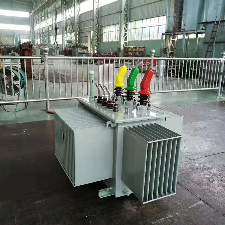
This series is designed for 10kV distribution networks, serving as the primary step-down equipment at the end of the power transmission line to supply 0.4kV low-voltage power to industrial, commercial, and residential loads. The design balances energy efficiency, noise levels, short-circuit withstand capability, and long-term operational reliability, fully complying with relevant IEC, GB, ANSI/IEEE, and NEMA standards.
Technical Specifications
|
Item |
Parameter |
|
Applicable standards |
IEC, GB, ANSI/IEEE, NEMA |
|
Rated capacity |
30 kVA to 2500 kVA |
|
Primary rated voltage |
6 kV, 10 kV, or 35 kV depending on model |
|
Secondary rated voltage |
0.4 kV |
|
Tapping range |
5 positions, off-circuit |
|
Rated frequency |
50 Hz or 60 Hz |
|
Phase |
Three-phase |
|
Connection symbol |
Dyn11, Yzn11, Yyn0 and others |
|
Short-circuit impedance |
4.0% / 4.5% / 5.0% by capacity range |
|
Cooling method |
ONAN (oil natural air natural) |
|
Insulation class |
Class A (oil-immersed) |
|
Voltage regulation |
Off-circuit tap changing |
Energy Efficiency Ratings and Loss Parameters
The table below lists the no-load and load losses for various capacity ratings across different energy efficiency levels. The data is based on batch test results using cold-rolled grain-oriented silicon steel sheets and a fully automated lamination process, complying with the limit requirements of GB 20052-2020.
|
Rated capacity |
Grade 1 |
Grade2 |
Grade3 |
Short-circuit impedance % |
||||||
|
Electrical steel strip |
Electrical steel strip |
Electrical steel strip |
||||||||
|
No-load loss W |
Load loss |
No-load loss W |
Load loss |
No-load loss
W |
Load loss |
|||||
|
Dyn11/Yzn11 |
Yyn0 |
Dyn11/Yzn11 |
Yyn0 |
Dyn11/Yzn11 |
Yyn0 |
|||||
|
30 |
65 |
455 |
430 |
70 |
505 |
480 |
80 |
630 |
600 |
4.0 |
|
50 |
80 |
655 |
625 |
90 |
730 |
695 |
100 |
910 |
870 |
|
|
63 |
90 |
785 |
745 |
100 |
870 |
830 |
110 |
1090 |
1040 |
|
|
80 |
105 |
945 |
900 |
115 |
1050 |
1000 |
130 |
1310 |
1250 |
|
|
100 |
120 |
1140 |
1080 |
135 |
1265 |
1200 |
150 |
1580 |
1500 |
|
|
125 |
135 |
1360 |
1295 |
150 |
1510 |
1440 |
170 |
1890 |
1800 |
|
|
160 |
160 |
1665 |
1585 |
180 |
1850 |
1760 |
200 |
2310 |
2200 |
|
|
200 |
190 |
1970 |
1870 |
215 |
2185 |
2080 |
240 |
2730 |
2600 |
|
|
250 |
230 |
2300 |
2195 |
260 |
2560 |
2440 |
290 |
3200 |
3050 |
|
|
345 |
270 |
2760 |
2630 |
305 |
3065 |
2920 |
340 |
3830 |
3650 |
|
|
400 |
330 |
3250 |
3095 |
370 |
3615 |
3440 |
410 |
4520 |
4300 |
|
|
500 |
385 |
3900 |
3710 |
430 |
4330 |
4120 |
480 |
5410 |
5150 |
|
|
630 |
460 |
4460 |
510 |
4960 |
570 |
6200 |
4.5 |
|||
|
800 |
560 |
5400 |
630 |
6000 |
700 |
7500 |
||||
|
1000 |
665 |
7415 |
845 |
8240 |
830 |
10300 |
||||
|
1250 |
780 |
8640 |
870 |
9600 |
970 |
12000 |
||||
|
1600 |
940 |
10440 |
1050 |
11600 |
1170 |
14500 |
||||
|
2000 |
1085 |
13180 |
1225 |
14640 |
1360 |
18300 |
5.0 |
|||
|
2500 |
1280 |
13360 |
1440 |
14840 |
1600 |
21200 |
||||
Note: The load losses listed in the table apply to Dyn11/Yzn11 vector groups; load losses for Yyn0 vector groups differ slightly. Please refer to the technical agreement associated with the order for specific details.
Structural and Manufacturing Features
Core
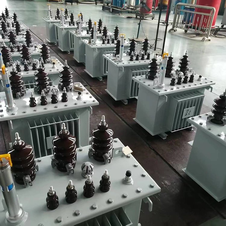
Constructed using high-permeability, cold-rolled grain-oriented silicon steel sheets, assembled via a fully automated robotic stacking machine. Cutting burrs are strictly controlled, and the stacking factor remains stable; compared to traditional manual stacking, no-load losses are reduced by 5% – 10%, with simultaneous reductions in no-load current and noise levels.
Windings
Low-voltage windings are wound using copper foil, while high-voltage windings are formed using adhesive-coated paper (bonded and cured under heat and pressure). Both structures offer high mechanical strength, enabling them to withstand repeated short-circuit electromagnetic forces and enhancing short-circuit withstand capability.
Insulation and Drying
After assembly, the active part undergoes treatment in a kerosene vapor phase vacuum drying system to remove moisture and gases from the insulation materials, thereby improving insulation performance and service life. The drying process is computer-controlled, with temperature and vacuum levels regulated according to preset curves.
Surface Treatment
The tank and external structural components undergo shot-blasting for rust removal, followed by electrostatic powder coating. The coating offers superior adhesion and uniformity compared to traditional liquid painting, providing effective weather resistance and corrosion protection.
Quality Assurance and Testing
The company holds ISO 9001:2015, ISO 14001, and ISO 45001 management system certifications. Before leaving the factory, all products in this series undergo routine tests in accordance with national standards and internal specifications, including winding DC resistance, voltage ratio, insulation resistance, power-frequency withstand voltage, induced withstand voltage, no-load loss, load loss, and short-circuit impedance. Type tests and special tests can be conducted in qualified laboratories based on customer requirements or standard specifications.
FAQs
Q: Can this transformer be used in 60Hz systems?
Yes. The design allows for adjustments to core magnetic flux density and winding turns to suit either 50Hz or 60Hz frequencies; loss and temperature rise verification are performed at the corresponding frequency prior to delivery.
Q: How should I choose between Dyn11 and Yyn0 connection groups?
Dyn11 is suitable for applications with significant unbalanced loads; it features low zero-sequence impedance and allows for the circulation of third-harmonic currents. Yyn0 features a simpler structure and is commonly used in distribution systems with relatively balanced three-phase loads. If both connection types are required, please specify this when ordering, as the low-voltage winding structure differs between them.
Q: Which power ratings correspond to short-circuit impedance values of 4.0%, 4.5%, and 5.0%?
Typically, 4.0% applies to ratings from 30 kVA to 500 kVA; 4.5% to 630 kVA – 1600 kVA; and 5.0% to 2000 kVA – 2500 kVA. Please refer to the technical parameter table in the contract for specific values.
Q: Can products with higher energy efficiency ratings be provided?
Yes. The "Level 1" rating listed in the table meets the higher energy efficiency requirements specified in GB 20052-2020. If a user requires even lower losses — such as through the use of amorphous alloy cores or other special designs — these can be evaluated as custom projects.
Q: Is customization for a 35 kV primary voltage supported?
Yes. The core structure and insulation design of this series can accommodate primary voltages ranging from 10 kV to 35 kV; however, main insulation clearances and internal assembly dimensions must be recalculated, which may extend the delivery lead time.
Applications
These 10kV oil-immersed stacked-core distribution transformers are suitable for scenarios such as urban and rural grid upgrades, power distribution for industrial and mining enterprises, commercial buildings, and step-up or step-down applications in new energy generation. For installations in high-altitude, high-humidity, or heavily polluted areas, external insulation clearances and tank protection ratings can be adjusted to meet specific operating environment requirements.
Please contact the Yulan Transformer sales or technical department to obtain dimension drawings, weight specifications, and installation foundation drawings for specific models
Related Category
Send Inquiry
Contact Info
-
Address
No. 20, Bai'e Road, Hecun Town, Jiangshan City, Zhejiang Province,CHINA
-
Tel
-
Email
Send specs for power, furnace or rectifier transformers and get a customized quotation and price list, direct from Yulan Transformer factory. Bulk orders welcome.
Related Products
News Recommendations




