
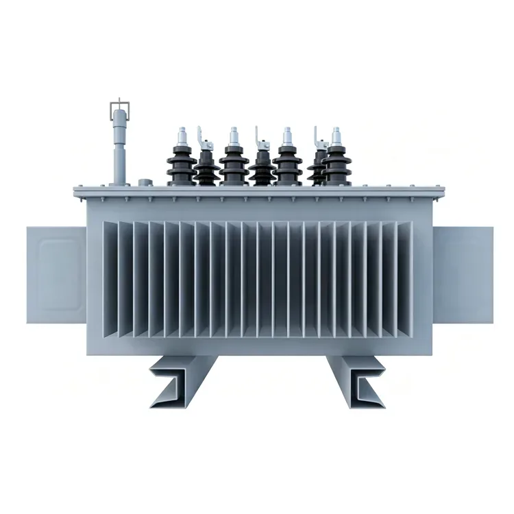
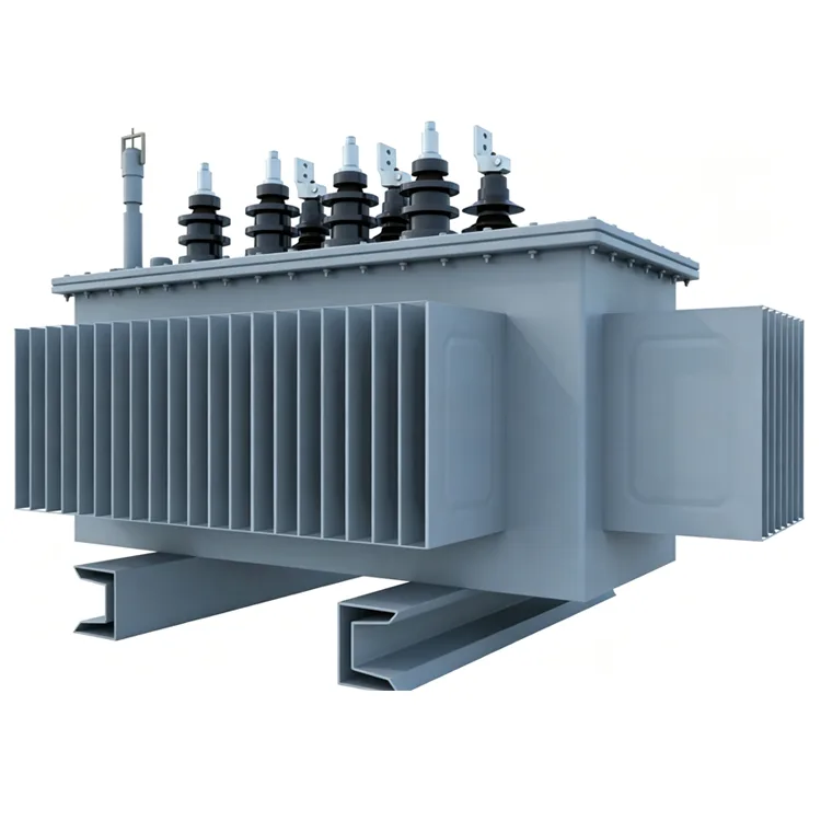
Oil-Immersed Amorphous Alloy Distribution Transformer
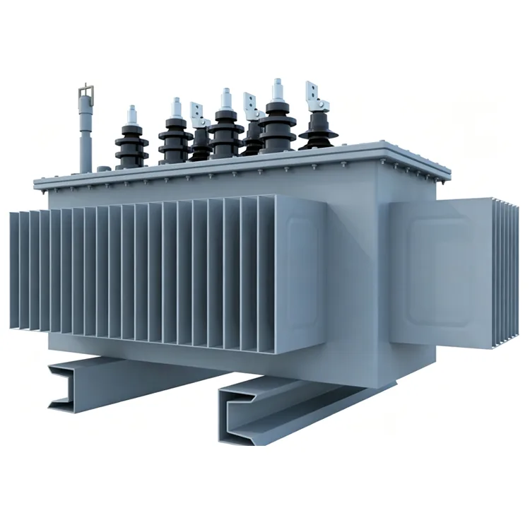
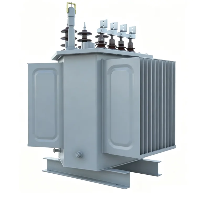
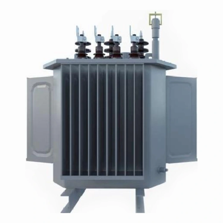
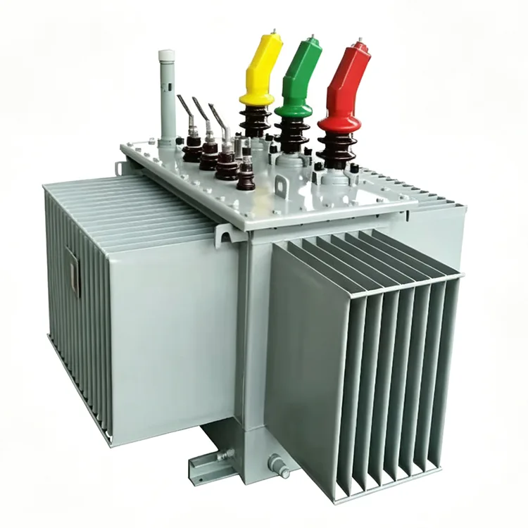
The 10kV Oil-Immersed Amorphous Alloy Distribution Transformer from Yulan Transformer is designed for high-efficiency medium-voltage power distribution. It features a 3D wound core structure and offers a capacity range of 30 to 2,500 kVA. Its seamless core design helps reduce no-load losses and operational noise, making it suitable for applications in power grids, as well as industrial and commercial sectors. We welcome inquiries regarding procurement, ordering, or customization for your projects.
The application of amorphous alloy materials in distribution transformers primarily addresses the issue of high no-load losses. In rural power grids, mountainous supply lines, and locations with intermittent power usage—where load factors remain consistently low—no-load losses often account for a larger share of total losses than load losses. Yulan Transformer manufactures 10kV Oil-Immersed Amorphous Alloy Distribution Transformers with capacities ranging from 30kVA to 2500kVA; they support primary voltages of 6kV, 10kV, or 35kV and a secondary output of 0.4kV. The manufacturing process utilizes the company's production and testing systems established for 110kV-class transformers, covering core-and-coil assembly drying, insulation treatment, and factory acceptance testing.
Characteristics of the Amorphous Alloy Core
The core is constructed from amorphous alloy strip material, resulting in no-load losses that are approximately one-third to one-fifth of those found in cold-rolled silicon steel cores of the same specification. Additionally, amorphous alloys exhibit low coercivity—leading to reduced exciting current—and superior thermal stability compared to some conventional silicon steel sheets. These characteristics yield significant energy savings in scenarios involving low load factors and long-term grid operation.
The core features a three-phase, five-limb wound structure, clamped by a formed thin-plate frame. Compared to planar stacked cores, the wound structure minimizes joints, enhances magnetic circuit continuity, and helps reduce noise levels.
Coil and Assembly Methods
The low-voltage coils are wound using copper foil, while the high-voltage coils are formed using adhesive-coated paper that is heat-cured under pressure. Both structures offer high mechanical strength, enabling them to withstand the electromagnetic forces generated during short-circuit events. Following assembly, the core-and-coil unit undergoes kerosene vapor phase vacuum drying to eliminate moisture and gases from the insulation materials. The oil tank and external structural components are shot-blasted to remove rust and then powder-coated; the coating's uniformity and adhesion meet the requirements for outdoor operation.
Technical Specifications
|
Item |
Standards |
|
Executive Standard |
IEC, GB, ANSI/IEEE, NEMA |
|
Rated Capacity |
30 kVA to 2500 kVA |
|
Primary Rated Voltage |
6 kV, 10 kV, 35 kV (depending on specific model) |
|
Secondary Rated Voltage |
0.4 kV |
|
Number of Taps |
5 taps (off-circuit tap changing) |
|
Rated Frequency |
50 Hz / 60 Hz |
|
Number of Phases |
Three-phase |
|
Vector Group |
Dyn11, Yyn0, etc. |
|
Short-circuit Impedance |
4.0% / 4.5% / 6.0% / 6.5% (varies by capacity range) |
|
Cooling Method |
ONAN (Oil-immersed natural cooling) |
|
Voltage Regulation Method |
Off-circuit tap changing |
Reference Data on Losses
The table below lists reference values for losses at specific rated capacities under Grade 1 energy efficiency standards. No-load losses for amorphous alloy cores are significantly lower than those of silicon steel transformers of the same capacity, while load losses are essentially comparable to those of conventional products.
|
Rated capacity KVA |
Level 1 |
Level2 |
Level3 |
Short-circuit impedance % |
||||||
|
Amorphous alloy |
Amorphous alloy |
Amorphous alloy |
||||||||
|
No-load loss W |
Load loss W |
No-load lossW |
Load loss W |
No-load loss W |
Load loss
|
|||||
|
Dyn11/Yzn11 |
Yyn0 |
Dyn11/Yzn11 |
Yyn0 |
Dyn11/Yzn11 |
Yyn0 |
|||||
|
30 |
25 |
510 |
480 |
33 |
535 |
510 |
33 |
630 |
500 |
4.0 |
|
50 |
35 |
735 |
700 |
43 |
780 |
745 |
43 |
910 |
8700 |
|
|
63 |
40 |
880 |
840 |
50 |
930 |
890 |
50 |
1090 |
1040 |
|
|
80 |
50 |
1060 |
1010 |
60 |
1120 |
1070 |
60 |
1310 |
1250 |
|
|
100 |
60 |
1270 |
1215 |
75 |
1350 |
1285 |
75 |
1580 |
1500 |
|
|
125 |
70 |
1530 |
1450 |
85 |
1615 |
1540 |
85 |
1890 |
1800 |
|
|
160 |
80 |
1870 |
1780 |
100 |
1970 |
1880 |
100 |
2310 |
2200 |
|
|
200 |
95 |
2210 |
2100 |
120 |
2330 |
2225 |
120 |
2730 |
2600 |
|
|
250 |
110 |
2590 |
2470 |
140 |
2735 |
2640 |
140 |
3200 |
3050 |
|
|
345 |
135 |
3100 |
2950 |
170 |
3275 |
3120 |
170 |
3830 |
3650 |
|
|
400 |
160 |
3660 |
3480 |
200 |
3865 |
3675 |
200 |
4520 |
4300 |
|
|
500 |
190 |
4380 |
4170 |
240 |
4625 |
4400 |
240 |
5410 |
5150 |
|
|
630 |
250 |
5020 |
320 |
5300 |
320 |
6200 |
4.5 |
|||
|
800 |
300 |
6075 |
380 |
5415 |
380 |
7500 |
||||
|
1000 |
360 |
8340 |
450 |
8800 |
450 |
10300 |
||||
|
1250 |
425 |
9720 |
530 |
10260 |
530 |
12000 |
||||
|
1600 |
500 |
11745 |
630 |
12400 |
630 |
14500 |
||||
|
2000 |
550 |
14000 |
710 |
14800 |
720 |
18300 |
5.0 |
|||
|
2500 |
670 |
15450 |
860 |
16300 |
865 |
21200 |
||||
Factory Acceptance Tests
Before leaving the factory, each unit undergoes tests including winding DC resistance, voltage ratio, insulation resistance, power-frequency withstand voltage, induced withstand voltage, no-load loss, load loss, and short-circuit impedance. The company holds ISO 9001:2015, ISO 14001, and ISO 45001 certifications.
FAQ
Q: Which users are best suited for amorphous alloy transformers?
They are best suited for applications with low load factors where the transformer remains energized for long periods but actual power consumption is low. In scenarios such as rural power grids, remote area power supply, and seasonal load fluctuations, the reduction in no-load loss yields direct savings in operating costs. If the load factor consistently exceeds 50%, silicon steel transformers may offer better overall economic efficiency.
Q: What are the disadvantages of amorphous alloy cores?
Amorphous alloy strips are thin and hard, making them more difficult to process and resulting in slightly higher manufacturing costs. Additionally, amorphous alloys are sensitive to mechanical stress; strong impacts must be avoided during transport and installation. They are also generally larger and heavier than silicon steel transformers of the same capacity.
Q: How is the noise performance?
Amorphous alloy transformers produce slightly higher noise levels than silicon steel transformers of the same capacity under no-load conditions due to differences in magnetostriction characteristics. However, through optimized clamping structures and tank design, noise levels can be kept within the limits required by the State Grid and China Southern Power Grid. Specific values should be evaluated based on capacity and the installation environment.
Q: Can they be used in 60Hz systems?
Yes. Since the magnetic properties of amorphous alloy cores vary with frequency, magnetic flux density and winding parameters must be recalculated for 60Hz operation; loss and temperature rise are verified at the corresponding frequency before the unit leaves the factory.
Q: Are there special requirements for transport and lifting?
The transformer body must remain upright. Lifting points on the top of the tank should be used; steel cables must not be tied directly to radiators or bushings. Amorphous alloy cores are sensitive to impact, so sudden braking and severe jolting should be avoided during transport. Upon arrival, it is recommended to check the oil level and sealing integrity before putting the unit into operation.
Application Scope
This product is suitable for rural power grid upgrades, mountainous power supply lines, distribution rooms in residential complexes, small industrial users, and distribution systems on the generation side of new energy projects. Amorphous alloy solutions offer distinct energy-saving advantages for sites characterized by consistently low load factors and sensitivity to no-load losses.
Please contact the Yulan Transformer sales or technical department for specific model dimensions, weights, or foundation installation drawings.
Related Category
Send Inquiry
Contact Info
-
Address
No. 20, Bai'e Road, Hecun Town, Jiangshan City, Zhejiang Province,CHINA
-
Tel
-
Email
Send specs for power, furnace or rectifier transformers and get a customized quotation and price list, direct from Yulan Transformer factory. Bulk orders welcome.
Related Products
News Recommendations




