
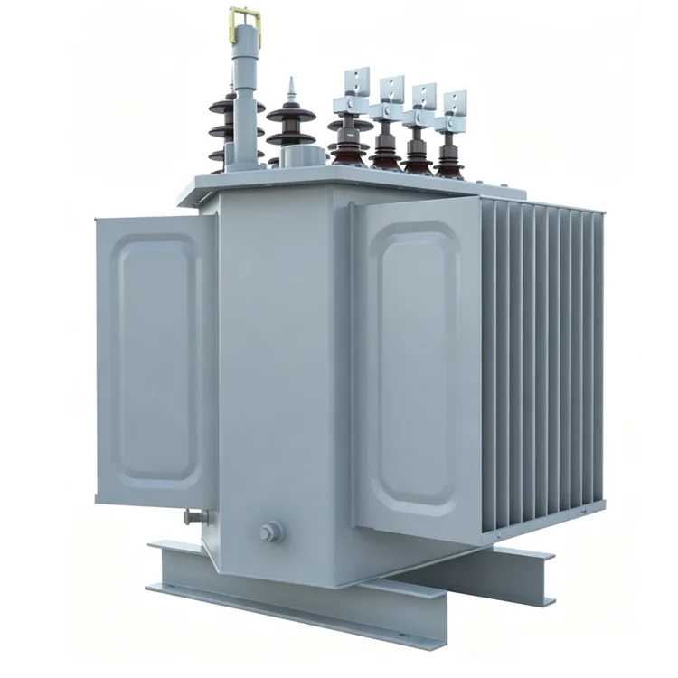
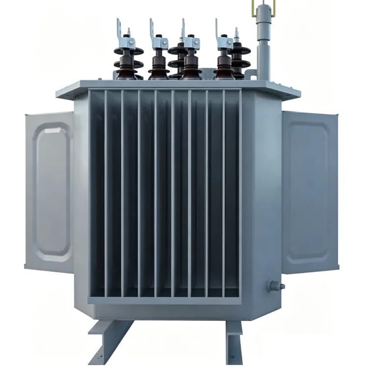
10kV Oil-Immersed Distribution Transformer With 3d Wound Core
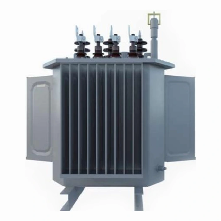
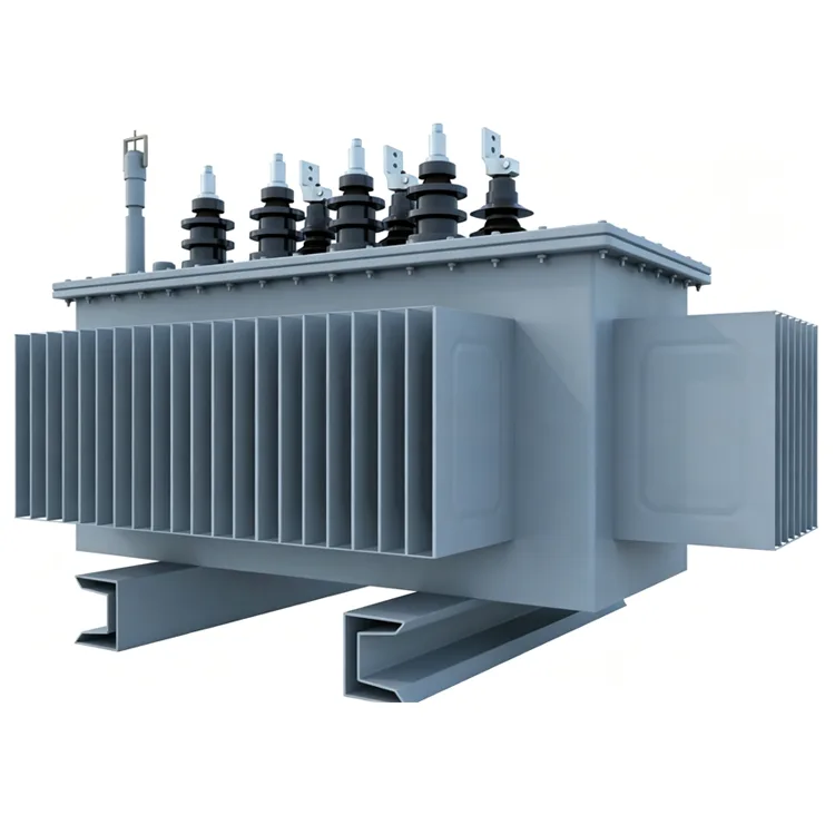
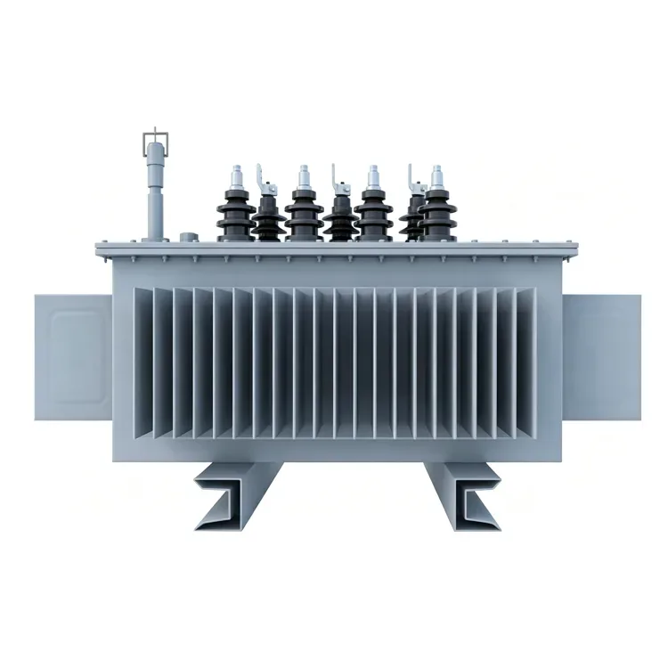
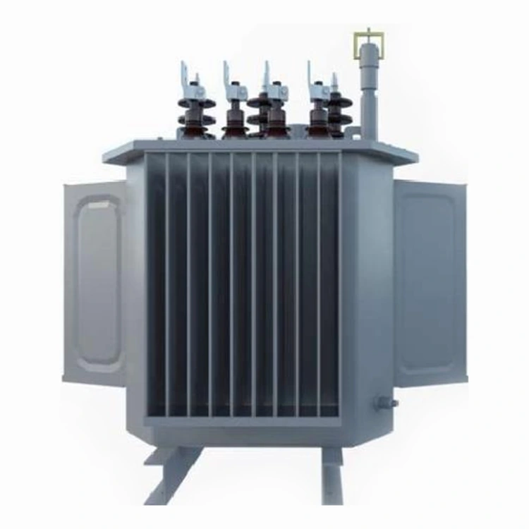
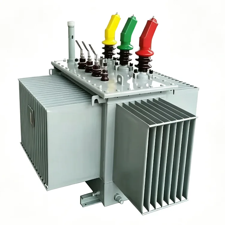
Yulan Transformer manufactures 10kV oil-immersed distribution transformers with three-dimensional wound cores, featuring rated capacities ranging from 30 kVA to 2,500 kVA. These10KV Oil-immersed distribution transformer with 3D wound core offers advantages such as low no-load losses and noise levels reduced by 3–5 dB, making them suitable for power grid, industrial, and commercial distribution applications. We welcome inquiries regarding procurement, ordering, or specification of this model for your projects.
When selecting 10kV distribution transformers, no-load loss and noise levels are key metrics that have long received significant attention. Traditional stacked-core structures are limited in their potential for further reducing loss and noise due to the presence of joints and inherent asymmetries in the magnetic circuit. In contrast, the 10KV Oil-immersed distribution transformer with 3D wound core utilizes a different forming method, resulting in equal magnetic path lengths across all three phases and eliminating joints entirely. Yulan Transformer applies this structural design to liquid-immersed distribution transformers with capacities ranging from 30kVA to 2500kVA; these units support primary voltages of 6kV, 10kV, or 35kV and a secondary output of 0.4kV.
Differences from Stacked-Core Structures
The 10KV Oil-immersed distribution transformer with 3D wound core is formed by winding continuous strips of grain-oriented silicon steel, eliminating lap joints in the magnetic circuit. The direction of magnetic flux aligns closely with the orientation of the silicon steel, leading to significantly lower no-load losses and no-load currents compared to stacked-core units of the same capacity. Furthermore, the equal lengths of the three-phase magnetic paths result in lower no-load current imbalance than traditional designs.
Regarding material utilization, the winding process minimizes scrap, typically resulting in a smaller footprint and lighter weight than stacked-core alternatives for the same capacity. Noise levels are also 3 to 5 dB lower, making these transformers suitable for indoor substations with strict acoustic requirements.
Manufacturing and Assembly
After winding, the core undergoes an annealing process to restore the magnetic properties of the silicon steel. Annealing temperatures and durations are controlled according to a precise curve, which directly influences the stability of no-load loss performance. Low-voltage coils are wound using copper foil, while high-voltage coils are formed using adhesive-coated paper that is heat-cured under pressure, ensuring mechanical strength sufficient to withstand short-circuit conditions.
Following assembly, the active part undergoes kerosene vapor phase vacuum drying to remove moisture and gases from the insulation materials. The tank and external structural components are shot-blasted to remove rust and then powder-coated; the resulting finish offers the uniformity and adhesion required for outdoor service.
Application Scenarios
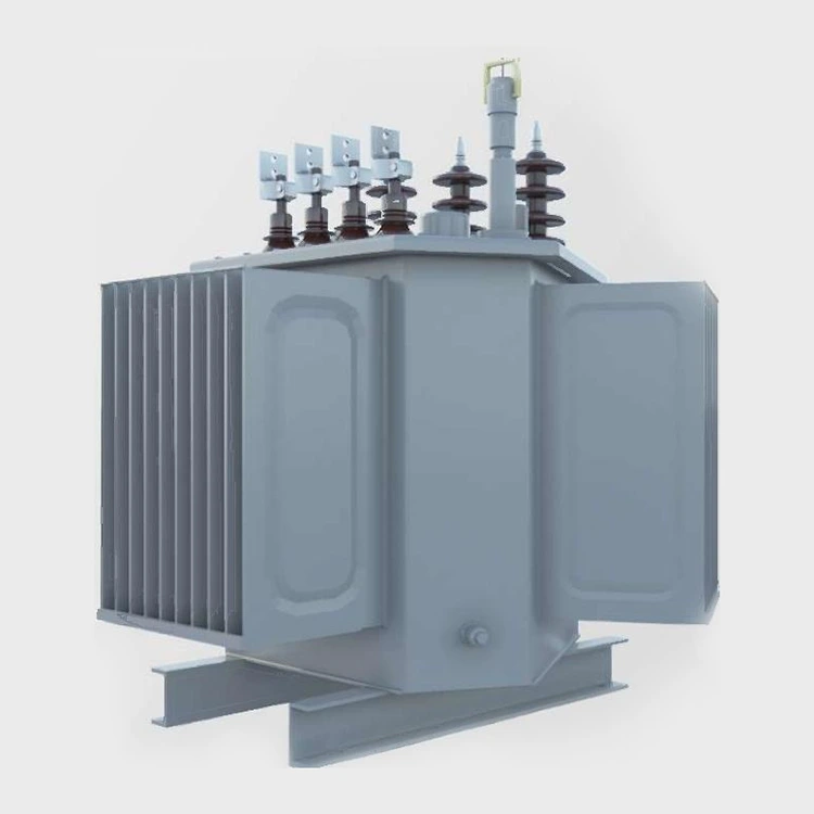
10KV Oil-immersed distribution transformer with 3D wound core is suitable for urban and rural grid upgrades, power distribution for industrial and mining enterprises, commercial buildings, and step-up or step-down applications in new energy generation. Their low-noise characteristics are particularly beneficial for noise-sensitive locations such as residential distribution rooms and indoor substations.
Technical Parameters
|
Item |
Standards |
|
Executive Standard |
IEC, GB, ANSI/IEEE, NEMA |
|
Rated Capacity |
30 kVA to 2500 kVA |
|
Primary Rated Voltage |
6 kV, 10 kV, 35 kV (depending on specific model) |
|
Secondary Rated Voltage |
0.4 kV |
|
Number of Taps |
5 taps (off-circuit tap changing) |
|
Rated Frequency |
50 Hz / 60 Hz |
|
Number of Phases |
Three-phase |
|
Vector Group |
Dyn11, Yyn0, etc. |
|
Short-circuit Impedance |
4.0% / 4.5% / 6.0% / 6.5% (varies by capacity range) |
|
Cooling Method |
ONAN (Oil-immersed natural cooling) |
|
Insulation Class |
Class A (Oil-immersed type) |
|
Voltage Regulation Method |
Off-circuit tap changing |
Energy Efficiency and Loss Data
The following data is based on cores made of electrical steel strip and batch test results, complying with the energy efficiency limit values specified in GB 20052-2020. Specific loss parameters can be obtained from the technical department based on the capacity range, or estimated by referencing the energy efficiency data for products of the same capacity using planar stacked cores; the no-load loss of the 3D wound core structure is typically 10% to 20% lower.
|
Rated capacity |
Level 1 |
Level2 |
Level3 |
Short-circuit impedance% |
|||||||||||||||
|
Electrical steel strip |
Amorphous alloy |
Electrical steel strip |
Amorphous alloy |
Electrical steel strip |
Amorphous alloy |
||||||||||||||
|
No-load loss W |
Load loss W |
No-load loss
W |
Load loss W |
No-load loss W |
Load loss W |
No-load loss W |
Load lossW |
No-load loss W |
Load loss W |
No-load loss W |
Load loss W |
||||||||
|
Dyn11/Yzn1 |
Yyn0 |
Dyn11/Yzn1 Yyn0 |
Dyn11/Yzn1 Yyn0 |
yn11/Yzn11 |
Yyn0 |
Dyn11/ 1 Yyn0 |
Dyn11/Yzn1 |
Yyn0 |
|||||||||||
|
30 |
65 |
455 |
430 |
25 |
510 |
480 |
70 |
505 |
480 |
33 |
535 |
510 |
80 |
630 |
600 |
33 |
630 |
600 |
4.0 |
|
50 |
80 |
655 |
625 |
35 |
735 |
700 |
90 |
730 |
695 |
43 |
780 |
745 |
100 |
910 |
870 |
43 |
910 |
8700 |
|
|
63 |
90 |
785 |
745 |
40 |
880 |
840 |
100 |
870 |
830 |
50 |
930 |
890 |
110 |
1090 |
1040 |
50 |
1090 |
1040 |
|
|
80 |
105 |
945 |
900 |
50 |
1060 |
1010 |
115 |
1050 |
1000 |
60 |
1120 |
1070 |
130 |
1310 |
1250 |
60 |
1310 |
1250 |
|
|
100 |
120 |
1140 |
1080 |
60 |
1270 |
1215 |
135 |
1265 |
1200 |
75 |
1350 |
|
150 |
1580 |
1500 |
75 |
1580 |
1500 |
|
|
125 |
135 |
1360 |
1295 |
70 |
1530 |
1450 |
150 |
1510 |
1440 |
85 |
1615 |
1540 |
170 |
1890 |
1800 |
85 |
1890 |
1800 |
|
|
160 |
160 |
1665 |
1585 |
80 |
1870 |
1780 |
180 |
185C |
1760 |
100 |
1970 |
1880 |
200 |
2310 |
2200 |
100 |
2310 |
2200 |
|
|
200 |
190 |
1970 |
1870 |
95 |
2210 |
2100 |
215 |
2185 |
2080 |
120 |
2330 |
2225 |
240 |
2730 |
2600 |
120 |
2730 |
2600 |
|
|
250 |
230 |
2300 |
2195 |
110 |
2590 |
2470 |
260 |
2560 |
2440 |
140 |
2735 |
2640 |
290 |
3200 |
3050 |
140 |
3200 |
3050 |
|
|
345 |
270 |
2760 |
2630 |
135 |
310C |
2950 |
305 |
3065 |
2920 |
170 |
3275 |
3120 |
340 |
3830 |
3650 |
170 |
3830 |
3650 |
|
|
400 |
330 |
3250 |
3095 |
160 |
3660 |
3480 |
370 |
3615 |
3440 |
200 |
3865 |
3675 |
410 |
4520 |
4300 |
200 |
4520 |
4300 |
|
|
500 |
385 |
3900 |
3710 |
190 |
4380 |
4170 |
430 |
4330 |
4120 |
240 |
4625 |
4400 |
480 |
5410 |
5150 |
240 |
5410 |
5150 |
|
|
630 |
460 |
4460 |
250 |
5020 |
510 |
4960 |
320 |
5300 |
570 |
6200 |
20 |
6200 |
4.5 |
||||||
|
800 |
560 |
5400 |
300 |
6075 |
630 |
6000 |
380 |
5415 |
700 |
7500 |
380 |
7500 |
|||||||
|
1000 |
665 |
7415 |
360 |
8340 |
845 |
8240 |
450 |
8800 |
830 |
10300 |
450 |
10300 |
|||||||
|
1250 |
780 |
8640 |
425 |
9720 |
870 |
9600 |
530 |
10260 |
970 |
12000 |
530 |
12000 |
|||||||
|
1600 |
940 |
10440 |
500 |
11745 |
050 |
11600 |
630 |
12400 |
1170 |
14500 |
630 |
14500 |
|||||||
|
2000 |
1085 |
13180 |
550 |
14000 |
1225 |
4640 |
710 |
14800 |
360 |
18300 |
720 |
18300 |
5.0 |
||||||
|
2500 |
1280 |
13360 |
670 |
15450 |
1440 |
14840 |
860 |
16300 |
1600 |
21200 |
|
|
|
||||||
FAQ
Q: Are there specific requirements regarding transport and installation orientation for 3D wound-core transformers?
A: Yes. The transformer body must remain upright during transport and installation; it should not be laid flat or tilted beyond specified angles. The tank base is designed to accommodate lifting and forklift operations; on-site positioning must follow the lifting instructions marked on the nameplate.
Q: How do the external dimensions compare to stacked-core products of the same capacity?
A: Typically, the volume is 10% to 15% smaller; while the height remains largely unchanged, the width and depth are slightly reduced. Please consult the specific model's outline drawing for exact dimensions, as the standard dimensions for stacked-core products cannot be directly applied.
Q: Does the annealing process affect the product's service life?
A: Annealing according to standard curves restores the magnetic properties of the silicon steel sheets to a stable state. Insufficient annealing leads to higher no-load losses, while excessive annealing may damage the insulation coating. At Yulan Transformer, winding and annealing processes are strictly controlled during mass production, with documented consistency.
Q: Can it be used in systems with high harmonic content?
A: The magnitude and order of harmonic currents on the load side must be evaluated. The 3D wound-core structure itself does not alter harmonic tolerance; if the harmonic distortion rate is high, please specify this when ordering so that winding design and temperature rise margins can be adjusted accordingly.
Q: Does this structure support on-load tap changing?
A: Yes, though the layout of tap leads and the internal tank space require redesign. Standard products feature off-circuit tap changing; versions with on-load tap changing have longer lead times.
Related Category
Send Inquiry
Contact Info
-
Address
No. 20, Bai'e Road, Hecun Town, Jiangshan City, Zhejiang Province,CHINA
-
Tel
-
Email
Send specs for power, furnace or rectifier transformers and get a customized quotation and price list, direct from Yulan Transformer factory. Bulk orders welcome.
Related Products
News Recommendations




