
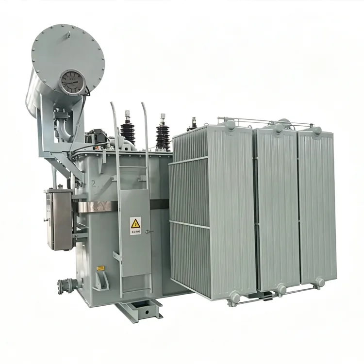
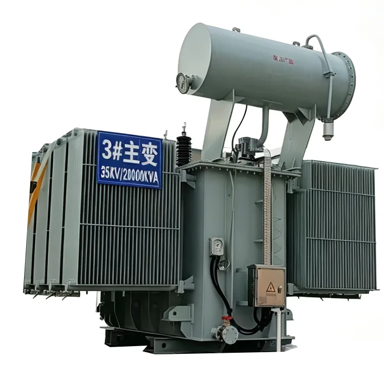
35kV Oil-Immersed Power Transformer
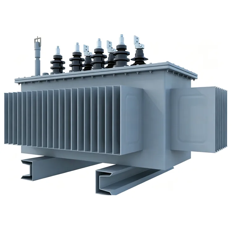
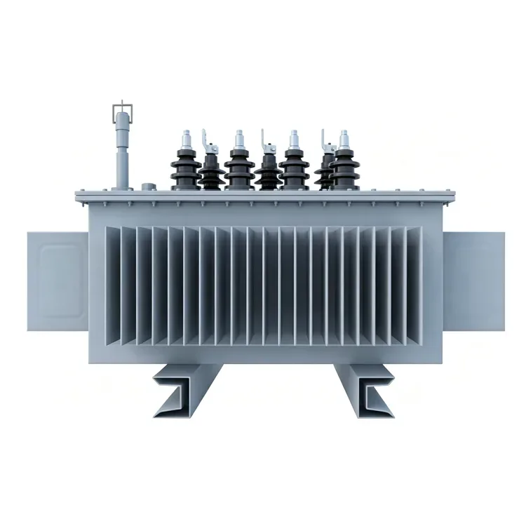
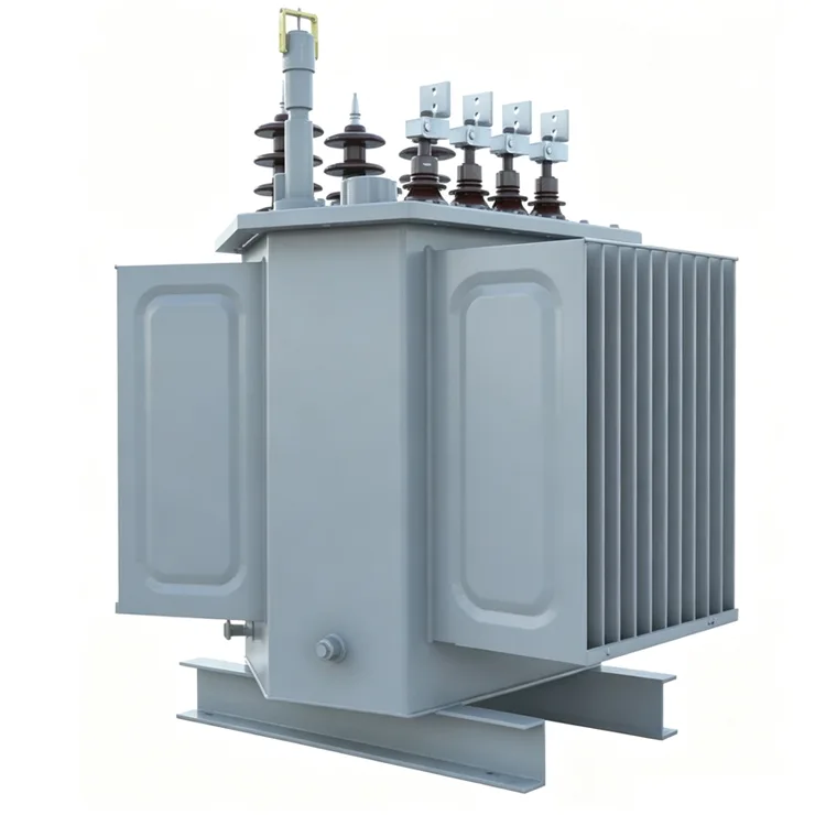
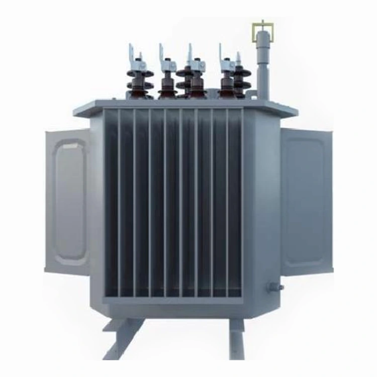
Yulan Transformer’s 35kV oil-immersed power transformers are specifically designed for substations, industrial power systems, and new energy applications. With a capacity range of 50–40,000 kVA and a primary voltage of 33–38.5 kV, this series meets customer needs for sourcing, procurement, and customization of reliable transformer solutions.
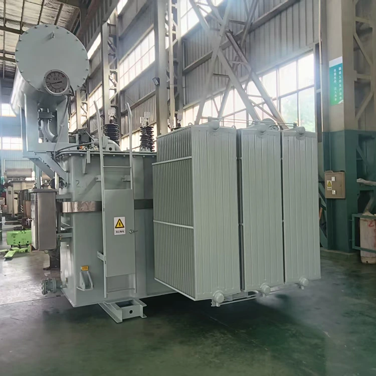
The 35kv Oil-immersed power transformer is suitable for regional substations, industrial user substations, and new energy collection and step-up applications. It features a primary voltage range of 33kV to 38.5kV, while the secondary voltage can be configured between 0.4kV and 11kV to meet specific system requirements. Yulan Transformer manufactures this series leveraging production and testing capabilities established for 110kV-class equipment; key processes include fully automated core stacking, kerosene vapor phase vacuum drying, and partial discharge testing. The products comply with relevant IEC, GB, ANSI/IEEE, and NEMA standards.
Technical Specifications
|
Item |
Parameter |
|
Applicable standards |
IEC, GB, ANSI/IEEE, NEMA |
|
Rated capacity |
50 kVA to 40,000 kVA |
|
Primary rated voltage |
33 kV to 38.5 kV |
|
Secondary rated voltage |
0.4 kV to 11 kV |
|
Tapping range |
5 to 9 positions, off-circuit |
|
Rated frequency |
50 Hz or 60 Hz |
|
Phase |
Three-phase |
|
Connection symbol |
Dyn11, Yyn0, Yd11, YNd11 and others |
|
Short-circuit impedance |
7% / 8% / 10% by capacity range |
|
Cooling method |
ONAN or ONAF |
|
Tank type |
Bell-type |
|
Conservator |
Expansion type |
Applications
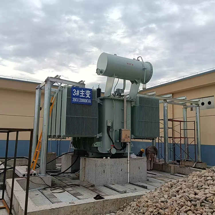
These 35kv Oil-immersed power transformers are suitable for main transformers or step-down transformers in 35kV substations, industrial user substations, collector and step-up applications in new energy power plants, and power distribution systems requiring a 35kV voltage level. For special environments — such as areas with heavy pollution, coastal salt spray, or high humidity — the external insulation design and the tank's protection rating can be adjusted.
Efficiency Grades and Loss Data
The table below lists no-load and load losses for common ratings from 3150 kVA and above under three efficiency grades, in kW. Values are based on cold-rolled grain-oriented silicon steel and batch test results, and they comply with the limits specified in GB 20052-2020.
|
Rated capacity KVA |
Level 1 |
Level 2 |
Level 3 |
Short-CircuitImpedance % |
|||
|
No-load loss |
Load loss W |
No-load loss |
Load loss W |
No-load loss |
Load loss W |
||
|
3150 |
1.7 |
20.7 |
2.0 |
20.7 |
2.4 |
21.9 |
7 |
|
4000 |
2.0 |
24.6 |
2.3 |
24.6 |
2.9 |
25.9 |
|
|
5000 |
2.4 |
28.2 |
2.8 |
28.2 |
3.5 |
29.7 |
|
|
6300 |
2.9 |
31.5 |
3.4 |
31.5 |
4.2 |
33.3 |
8 |
|
8000 |
4.0 |
34.6 |
4.7 |
34.6 |
5.8 |
36.5 |
|
|
10000 |
4.8 |
40.8 |
5.7 |
40.8 |
7.0 |
43.0 |
|
|
12500 |
5.5 |
48.4 |
6.5 |
48.4 |
8.0 |
51.1 |
|
|
16000 |
6.7 |
59.2 |
7.9 |
59.2 |
9.7 |
62.5 |
|
|
20000 |
7.9 |
71.6 |
9.4 |
71.6 |
11.5 |
75.5 |
|
|
25000 |
9.4 |
84.6 |
11.1 |
84.6 |
13.6 |
89.3 |
10 |
|
31500 |
11.1 |
100.8 |
13.1 |
100.8 |
16.2 |
106.4 |
|
Note: Loss data for ratings between 50 kVA and 2500 kVA is available upon request. Load loss figures are reference values based on standard vector groups; specific values are subject to the technical agreement.
Key Design and Manufacturing Details
Core and Windings
The core utilizes high-permeability, cold-rolled grain-oriented silicon steel sheets. Lamination is performed using fully automated equipment, with burrs and the lamination factor maintained within stable limits. Windings feature a disc-type structure; high- and low-voltage windings are configured with molded insulation components tailored to their respective insulation classes, ensuring overall mechanical strength meets short-circuit withstand requirements.
Active Part Insulation
After assembly, the active part undergoes a kerosene vapor-phase vacuum drying process to remove moisture and gases from the insulation components. The drying process follows preset temperature and vacuum curves, helping to minimize partial discharge levels and extend insulation lifespan.
Tank and Sealing
The tank features a bell-type structure, facilitating the lifting and inspection of the active part. Sealing flanges utilize a groove design, the oil drain valve is made of brass, and radiator connections are equipped with vacuum butterfly valves. These measures are implemented to reduce the risk of leakage during operation.
Noise and Partial Discharge Control
Noise levels under self-cooling conditions are controlled below 60 dB, and factory test values for partial discharge do not exceed 100 pC. Actual values depend on capacity, cooling method, and installation environment, and can be specified in the contract.
Surface Treatment
The tank and external structural components undergo shot-blasting for rust removal followed by powder coating. The coating offers superior uniformity and adhesion compared to traditional liquid paints and provides good outdoor weather resistance.
Quality Assurance and Factory Testing
The company holds ISO 9001:2015, ISO 14001, and ISO 45001 certifications. Every unit undergoes routine testing before leaving the factory, including winding DC resistance, voltage ratio, insulation resistance, power-frequency withstand voltage, induced withstand voltage, no-load loss, load loss, short-circuit impedance, and insulating oil tests. Type tests and special tests can be performed according to customer requirements or applicable standards.
FAQ
Q: Can the secondary voltage be 11 kV?
Yes. Secondary voltages can be designed within the 0.4 kV to 11 kV range, though winding structure, insulation clearances, and tank dimensions will be adjusted accordingly. Specific voltage and vector group requirements must be specified when ordering.
Q: Are there only three short-circuit impedance settings: 7%, 8%, and 10%?
The table lists the standard impedance values for the corresponding capacity ranges. If the system has specific impedance requirements, these can be evaluated and adjusted during the design phase, though such changes may affect losses and physical dimensions.
Q: Is an on-load tap-changing version available?
Yes. The standard configuration for this series is off-circuit tap-changing; if on-load tap-changing is required, an on-load tap changer must be installed and the tank structure modified, which will extend the delivery lead time.
Q: Under what conditions is the noise level of below 60 dB measured?
This figure applies to standard measurement distances under self-cooling conditions at rated voltage and frequency, typically in accordance with GB/T 1094.10 or IEC 60076-10. Actual on-site noise levels are influenced by factors such as installation method and wall reflections.
Q: Is this series suitable for high-altitude regions?
Yes. External insulation clearances and heat dissipation specifications can be adjusted based on altitude; parameters such as the installation site's altitude and ambient temperature must be provided when ordering.
Related Category
Send Inquiry
Contact Info
-
Address
No. 20, Bai'e Road, Hecun Town, Jiangshan City, Zhejiang Province,CHINA
-
Tel
-
Email
Send specs for power, furnace or rectifier transformers and get a customized quotation and price list, direct from Yulan Transformer factory. Bulk orders welcome.
Related Products
News Recommendations




