
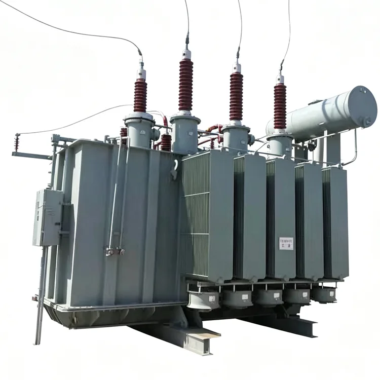
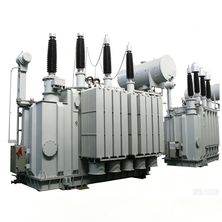
Oil-Immersed Three-Phase Three-Winding Power Transformer
Yulan Transformer supplies Oil-Immersed Three-Phase Three-Winding Power Transformers up to 110kV, 120,000 kVA. One tank integrates HV, MV and LV windings, saving floor area and reducing high-voltage terminations. Custom voltage ratings, tap changers and cooling available. IEC/GB compliant. Request a quote or place an order.
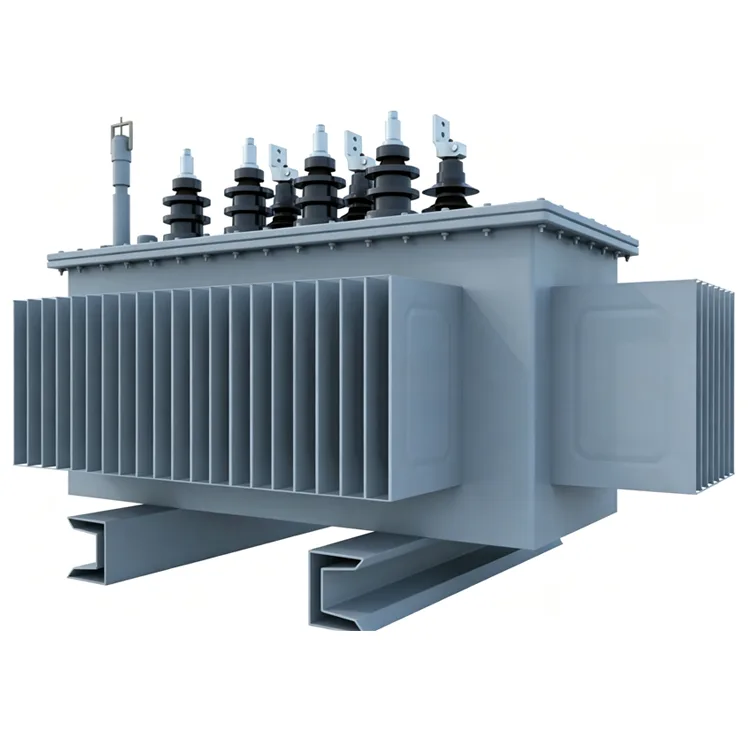
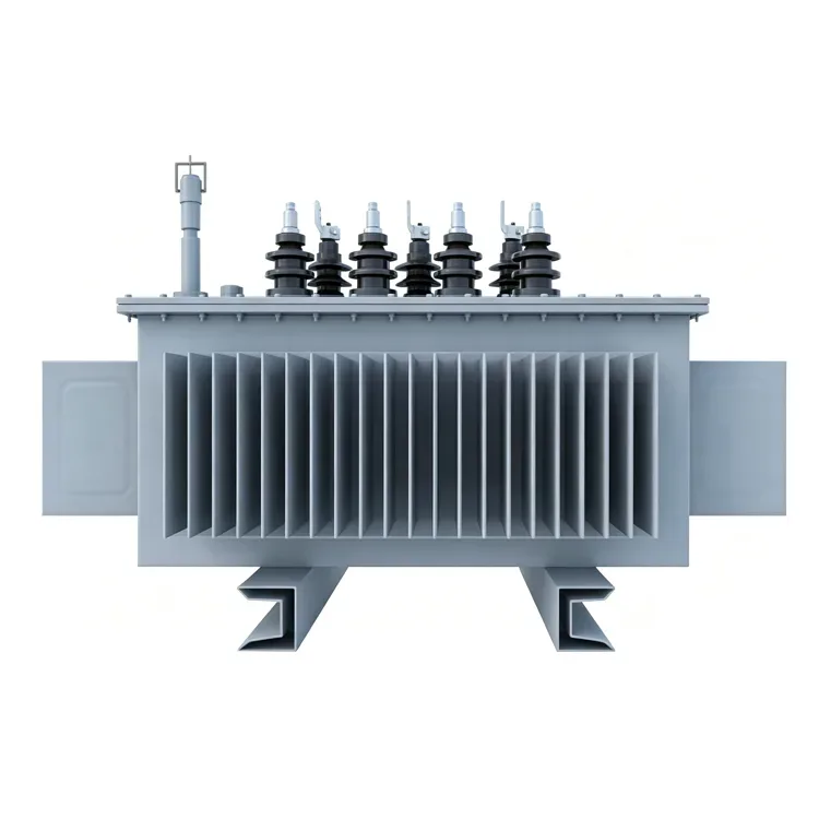
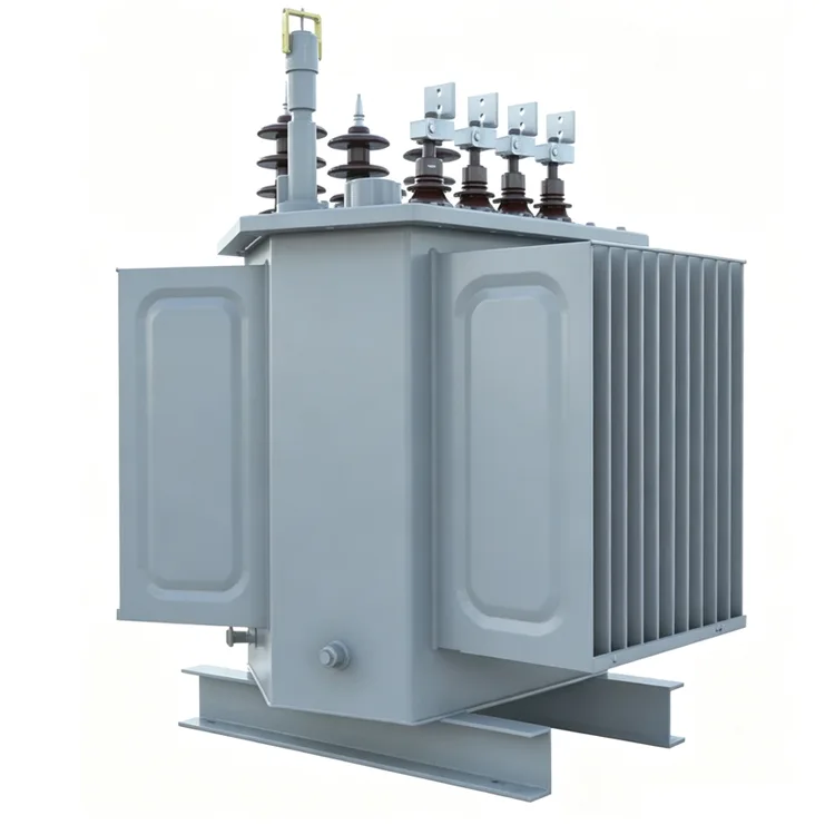
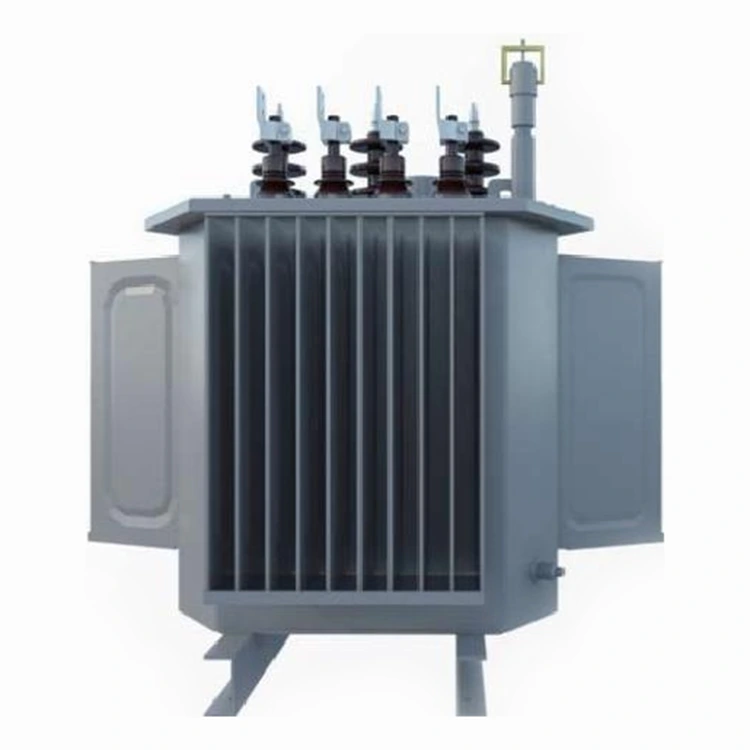
A three-winding unit brings together high, medium, and low voltage systems inside a single oil-filled tank. Instead of installing two separate two-winding transformers, a substation can use one three-winding design. This Oil-Immersed Three-Phase Three-Winding Power Transformer reduces the number of high-voltage terminations, saves floor area, and simplifies the overall station layout. Yulan Transformer supplies these units up to 110kV class, with single-unit capacity reaching 120,000 kVA.
Function and Voltage Arrangement
The Oil-Immersed Three-Phase Three-Winding Power Transformer has one primary winding and two secondary windings, each rated for a different system voltage. A typical configuration is 110kV on the high-voltage side, 38.5kV or 35kV on the medium-voltage side, and 10.5kV or 6.6kV on the low-voltage side. The exact voltage combination is determined during the design review.
Load can be taken from all three windings simultaneously. The power split between medium-voltage and low-voltage terminals depends on the winding capacity ratings agreed with the customer. In some projects, the medium-voltage winding is designed for full rated capacity while the low-voltage winding carries only a smaller auxiliary load.
Magnetic Circuit and Core Assembly
Grain-oriented silicon steel is used for the core laminations. The joints are cut at 45 degrees and assembled in a step-lap pattern. This arrangement aligns the flux path with the rolling direction of the steel across each joint, reducing localised saturation and lowering magnetising current.
The core legs and yokes are clamped with steel frames to prevent movement during transport and short-circuit events. Core earthing is brought out to a single bushing on the tank cover so that insulation resistance can be monitored during site commissioning.
Winding Design and Short-Circuit Performance
Each winding is calculated with transformer design software before production. The radial and axial amp-turn distributions are balanced to limit stray flux and minimise eddy losses in structural parts.
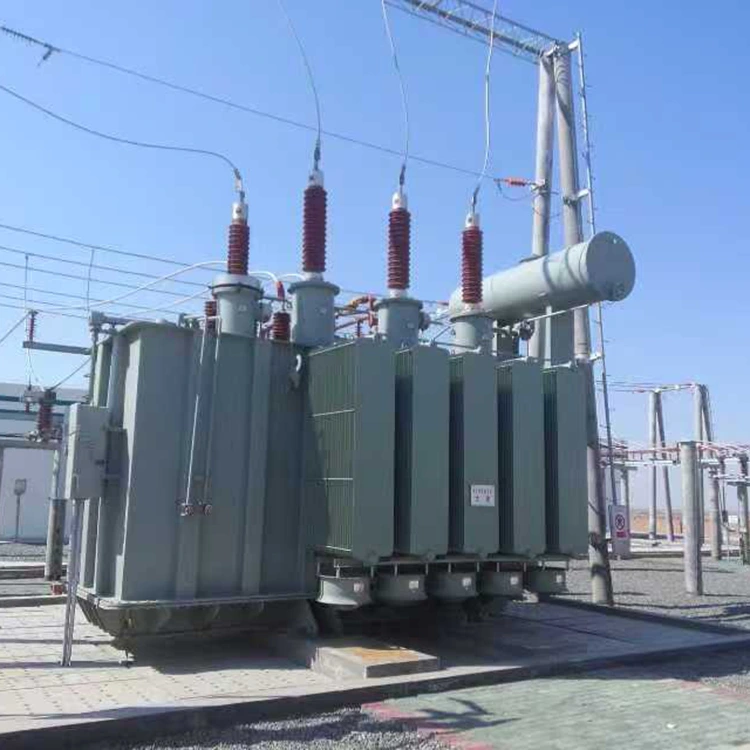
Winding conductors are copper, insulated with paper or enamel depending on voltage class and current rating. The high-voltage winding is normally placed outside the medium-voltage and low-voltage windings. This arrangement gives better access for tap leads and improves impedance control.
Short-circuit forces between windings are calculated for all specified fault conditions. The winding supports, spacers, and clamping structures are dimensioned accordingly. If a customer requires a short-circuit test certificate, the unit can be subjected to a dynamic short-circuit test at a recognised laboratory.
Tap Changing and Voltage Regulation
Voltage adjustment is provided on the high-voltage winding. Two options are available.
Off-circuit tap changer
The transformer must be de-energised before the tap position is changed. The tapping range is normally ±2×2.5% or ±5%, but other ranges can be supplied. This option is suitable for installations where the grid voltage is stable and frequent adjustment is not needed.
On-load tap changer
The tap position can be changed while the transformer carries load. Tapping ranges such as ±8×1.25% are common for 110kV transformers. The tap changer can be specified from a preferred manufacturer. Motor drive, remote indication, and automatic voltage control interfaces can be included.
Tank, Cooling and Preservation
The tank is designed to withstand full vacuum during oil filling at the factory. Lifting lugs, jacking pads, and towing eyes are provided for transport and installation. The cover is bolted and sealed with oil-resistant gaskets. Bushings are arranged according to the customer's preferred layout.
Cooling is normally natural oil natural air for smaller ratings. For larger units, detachable radiators with cooling fans are used. The fan control panel starts and stops the fans based on winding temperature or oil temperature. If the site has high ambient temperature, the cooling class is selected with an appropriate margin.
A conservator with a silica gel breather is used on this power transformer class. The Buchholz relay is mounted in the pipe between tank and conservator. A magnetic oil level gauge, winding temperature indicator, oil temperature indicator, and pressure relief device are included as standard.
Standards and Verification
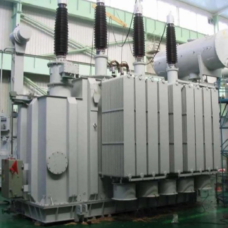
Design, manufacture, and testing follow IEC 60076. Chinese national standards such as GB 1094 and GB/T 6451 are applied where relevant. When a customer has specific requirements from another standard, the technical proposal is adjusted accordingly.
Before dispatch, each transformer passes routine tests. These cover winding resistance, ratio and vector group, insulation resistance, dielectric loss, separate-source withstand, induced overvoltage, no-load loss and current, load loss, and short-circuit impedance. Type tests and special tests, including lightning impulse, temperature rise, noise level, and short-circuit withstand, can be arranged on request.
Reference Parameter Table
The values below are typical for a 110kV / 38.5kV / 10.5kV three-winding transformer with on-load tap changer. Final parameters are confirmed in the technical agreement. No-load and load losses are subject to the applicable standard edition and customer's guaranteed loss evaluation.
|
Rated Capacity (kVA) |
HV (kV) |
MV (kV) |
LV (kV) |
Vector Group |
No-load Loss (kW) |
Load Loss HV-MV (kW) |
Impedance HV-MV (%) |
Impedance HV-LV (%) |
Impedance MV-LV (%) |
Overall Dimension L×W×H (mm) |
Total Weight (t) |
|
6,300 |
110±8×1.25% |
38.5 |
10.5 |
YNyn0d11 |
8.5 |
42 |
10.5 |
17.5 |
6.5 |
4600×3600×4300 |
18.5 |
|
8,000 |
110±8×1.25% |
38.5 |
10.5 |
YNyn0d11 |
10.2 |
50 |
10.5 |
17.5 |
6.5 |
4800×3700×4400 |
21.0 |
|
10,000 |
110±8×1.25% |
38.5 |
10.5 |
YNyn0d11 |
12.0 |
59 |
10.5 |
17.5 |
6.5 |
5000×3800×4500 |
24.5 |
|
12,500 |
110±8×1.25% |
38.5 |
10.5 |
YNyn0d11 |
14.2 |
70 |
10.5 |
17.5 |
6.5 |
5200×3900×4600 |
28.0 |
|
16,000 |
110±8×1.25% |
38.5 |
10.5 |
YNyn0d11 |
17.0 |
84 |
10.5 |
17.5 |
6.5 |
5400×4000×4700 |
32.5 |
|
20,000 |
110±8×1.25% |
38.5 |
10.5 |
YNyn0d11 |
20.0 |
100 |
10.5 |
17.5 |
6.5 |
5600×4100×4800 |
37.0 |
|
25,000 |
110±8×1.25% |
38.5 |
10.5 |
YNyn0d11 |
23.8 |
118 |
10.5 |
17.5 |
6.5 |
5800×4200×4900 |
42.0 |
|
31,500 |
110±8×1.25% |
38.5 |
10.5 |
YNyn0d11 |
28.5 |
140 |
10.5 |
17.5 |
6.5 |
6100×4300×5000 |
49.0 |
|
40,000 |
110±8×1.25% |
38.5 |
10.5 |
YNyn0d11 |
34.0 |
166 |
10.5 |
17.5 |
6.5 |
6400×4400×5100 |
57.0 |
|
50,000 |
110±8×1.25% |
38.5 |
10.5 |
YNyn0d11 |
40.5 |
198 |
10.5 |
17.5 |
6.5 |
6700×4500×5200 |
66.0 |
|
63,000 |
110±8×1.25% |
38.5 |
10.5 |
YNyn0d11 |
48.0 |
235 |
10.5 |
17.5 |
6.5 |
7000×4600×5300 |
78.0 |
Notes:
● Loss values correspond to rated capacity at rated voltage.
● Impedance values are given at rated capacity and can be adjusted within standard tolerances.
● Dimensions and weights are for reference. Final values depend on tap changer type, radiator size, and site accessories.
Project-Specific Questions
What if the station requires a different medium voltage, such as 22kV or 33kV?
The medium-voltage winding can be designed for any standard level within the insulation class of the transformer. The specification stage should include the exact system voltage and the required capacity split between secondary windings.
Is it possible to operate the medium and low voltage windings at different power factors?
Yes. The transformer does not require both secondary windings to supply the same type of load. Each winding is rated independently, and the design considers the heating effect of the combined losses.
Does a three-winding transformer need a special protection scheme?
The protection scheme usually includes differential protection covering all three windings, plus overcurrent and earth fault protection on each side. The transformer itself does not require additional protection devices beyond standard equipment such as the Buchholz relay and pressure relief device.
What is the typical delivery lead time for a 110kV three-winding unit?
For standard ratings, production and testing normally take four to six months after technical agreement is signed. Custom voltage combinations or special accessories may extend the schedule. Transport planning should be confirmed early because larger units require special permits in some regions.
Can Yulan Transformer provide supervision during installation and commissioning?
Yes. Site supervision, oil processing guidance, and commissioning support are available. The service scope can be arranged as part of the supply contract or as a separate item.
Quality Records and Traceability
Each transformer has a dedicated manufacturing file. The file includes material certificates, winding inspection records, core loss test data, tank weld inspection reports, and final routine test results. This documentation is retained after delivery and can be provided to the owner or the consulting engineer for review.
Yulan Transformer maintains quality management certification to ISO 9001:2015. Environmental and occupational health management follow ISO 14001 and ISO 45001:2018. Factory testing is carried out under the framework of IEC 60076 and GB 1094, and the test equipment is regularly calibrated.
Related Category
Send Inquiry
Contact Info
-
Address
No. 20, Bai'e Road, Hecun Town, Jiangshan City, Zhejiang Province,CHINA
-
Tel
-
Email
Send specs for power, furnace or rectifier transformers and get a customized quotation and price list, direct from Yulan Transformer factory. Bulk orders welcome.
Related Products
News Recommendations




